2. Connection and configuration
Connection and configuration
Safety rules
Before use, configure the system. Proper operation of the BMS is possible only if it is correctly configured.
Device connectors
The location and designation of the connectors are shown in figure below.
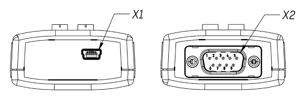
Х1 – mini-USB connector for communication with PC.
X2 – DB-9 connector for connecting to CAN bus.
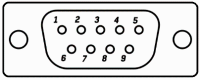
| Pin | Name | Description |
| 1 | - | - |
| 2 | CAN_L | CANL line of CAN bus |
| 3 | GND | Ground |
| 4 | - | - |
| 5 | - | - |
| 6 | - | - |
| 7 | CAN_H | CANH line of CAN bus |
| 8 | - | - |
| 9 | +5V | External device power supply |
Settings
If the BMS USB-CAN is connected to a PC, it is recognized as a common USB Serial Port. Remember the port number, it will be needed later during connection to the CAN bus.
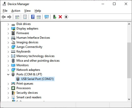
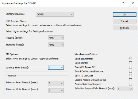
Before using the BMS USB-CAN decrease the “Latency Timer” for correct operation. To do this, right-click on the “USB Serial Port” and select “Properties”.
In the opened window, select the “Port settings” tab and click the “Advanced” button.
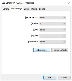
In the opened window, set the “Latency Timer” to the minimum value of 1 ms.
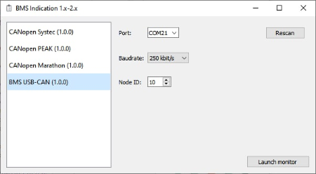
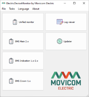
To connect to the CAN bus, start the ElectricDeviceMonitor software and open the corresponding monitor.
In the interface settings, select the “BMS USB-CAN” in the list of CANopen interfaces. Then, select the port, which was previously specified in the Device Manager, set the bus speed and device ID. Then, click on the “Launch monitor” button.