
2. Installation and connection
Installation and connection
Safety rules
To perform the protection functions, the BMS must be able to disconnect the battery from the load and charger. To do this, at least one contactor able to break the load and charge circuits must be connected to the BMS.
Before use, configure the system. Proper operation of the BMS is possible only if it is correctly configured.
Installation
The mounting area of the BMS Main X must be protected from mechanical particles (dust, dirt, large objects) and water.
The installation site must provide convenient access for subsequent connection to the device’s headers for connecting other system elements: contactors, temperature sensors, etc.
Overall and mounting dimensions of the BMS Main X are shown below.


Parameter | Value |
Overall dimensions (length × width × height), mm | 105 × 115 × 15 |
| Mounting dimensions (length × width), mm | 99 × 109 |
| Mounting holes | M3 |
Connection
Headers
There are names and locations of the BMS Main X headers in figure below.

Х1 – header for power supply
Receptacle Housing: Molex 436450200. Terminals: Molex 43030

| Pin | Name | Description |
| 1 | V+ | Supply voltage 18÷36V |
| 2 | GND | Ground |
X2 – header for USB
X3 – header for CAN (INT) interface
Receptacle Housing: Molex 430250400. Terminals: Molex 43030

| Pin | Name | Description |
| 1 | СAN_INT_H | CAN-H line of the internal CAN bus (communication with battery modules) |
| 2 | CAN_INT_L | CAN-L line of the internal CAN bus (communication with battery modules) |
| 3 | CAN_INT_5V | Isolated 5V power supply for internal devices, max 200 mA |
| 4 | CAN_INT_GND | Isolated ground |
Х4 – header for RS-485 interface
Receptacle Housing: Molex 430250400. Terminals: Molex 43030
| Pin | Name | Description |
| 1 | RS485_A | A line of the external RS-485 bus |
| 2 | RS485_B | B line of the external RS-485 bus |
| 3 | - | - |
| 4 | RS485_GND | Isolated ground |
J1 – jumper for switching RS-485 terminal resistor
To connect the terminal resistor between the RS485_A and RS485_B lines, install the jumper J1 according to the following figure:
Х5 – header for CAN (EXT) interface
Receptacle Housing: Molex 430250400. Terminals: Molex 43030
| Pin | Name | Description |
| 1 | СAN_EXT_H | CAN-H line of the external CAN bus (communication with a top-level system) |
| 2 | CAN_EXT_L | CAN-L line of the external CAN bus (communication with a top-level system) |
| 3 | CAN_EXT_5V | Isolated 5V power supply for external devices, max 200 mA |
| 4 | CAN_EXT_GND | Isolated ground |
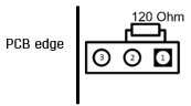
J2 – jumper for switching CAN (EXT) terminal resistor
To connect the terminal resistor between the CAN_EXT_H and CAN_EXT_L lines, install the jumper J2 according to the following figure:
Х6 – header for sold-state relays
Receptacle Housing: Molex 430250600. Terminals: Molex 43030

| Pin | Name | Description |
| 1 | NO1 | Normally open contact of the relay 1 |
| 2 | NO2 | Normally open contact of the relay 2 |
| 3 | NO3 | Normally open contact of the relay 3 |
| 4 | COM1 | Common contact of the relay 1 (55V, 2A) |
| 5 | COM2 | Common contact of the relay 2 (55V, 2A) |
| 6 | COM3 | Common contact of the relay 3 (55V, 2A) |
X7 – header for discrete inputs/outputs
Receptacle Housing: Molex 430251800. Terminals: Molex 43030

| Pin | Name | Description |
| 1 | GND | Discrete input 1 “dry contact” (ground) |
| 2 | GND | Discrete input 2 “dry contact” (ground) |
| 3 | GND | Discrete input 3 “dry contact” (ground) |
| 4 | GND | Discrete input 4 “dry contact” (ground) |
| 5 | - | - |
| 6 | GND | Discrete output 1 (ground) |
| 7 | GND | Discrete output 2 (ground) |
| 8 | GND | Discrete output 3 (ground) |
| 9 | GND | Discrete output 4 (ground) |
| 10 | D_IN1 | Discrete input 1 “dry contact” (+5V) |
| 11 | D_IN2 | Discrete input 2 “dry contact” (+5V) |
| 12 | D_IN3 | Discrete input 3 “dry contact” (+5V) |
| 13 | D_IN4 | Discrete input 4 “dry contact” (+5V) |
| 14 | - | - |
| 15 | D_OUT1 | Discrete output 1 (+5V, 20mA) |
| 16 | D_OUT2 | Discrete output 2 (+5V, 20mA) |
| 17 | D_OUT3 | Discrete output 3 (+5V, 20mA) |
| 18 | D_OUT4 | Discrete output 4 (+5V, 20mA) |
Х8 – header for temperature sensors
Receptacle Housing: Molex 430250400. Terminals: Molex 43030
| Pin | Name | Description |
| 1 | TEMPG1 | Ground of the thermistor 1 |
| 2 | TEMPG2 | Ground of the thermistor 2 |
| 3 | TEMP1 | Signal from the thermistor 1 |
| 4 | TEMP2 | Signal from the thermistor 2 |