

3.5 External equipment
Settings
External equipment
The BMS Main 3X / BMS Main 2RX device supports joint operation with vehicle controllers.
BKM controller
Communication parameters for the BKM controller are configured in the section "External equipment - BKM controller":

In this section:
- Enable – a flag to enable communication with the BKM controller;
- CAN port – port which is used to communicate with the charger:
- CAN1 (ext);
- CAN2 (int);
- Receive timeout – a timeout for receiving packets from the controller (if no data is received from the BKM controller during this time, then the communication loss flag is set), ms;
- Maximum voltage – a maximum charge voltage, V;
- Maximum current – a maximum charge current, A;
- SOC of the partially charger battery – a charge level of the partially charged battery, %;
- SOC of the fully charger battery – a charge level of the fully charged battery, %.
Basic J1939 vehicle
The basic vehicle protocol J1939 is developed by Movicom Electric, and its description is available upon request. Using this protocol, information about the parameters of the modular battery can be obtained. The protocol also implements the management of battery operation modes.
Communication parameters via the Basic J1939 protocol are configured in the “External equipment – Basic J1939 vehicle” section:

In this section:
- Enable – a flag to enable communication using the protocol;
- CAN port – port which is used to communicate with the vehicle:
- CAN1 (ext);
- CAN2 (int);
- BMS message ID – an identifier of the first message of the device in the J1939 network;
- Vehicle Message ID – an identifier of the first message of the vehicle in the J1939 network.
Evocargo vehicle
Communication parameters for the Evocargo vehicle are configured in the section "External equipment – Evocargo vehicle":

In this section:
- Enable – a flag to enable communication with the Evocargo vehicle;
- CAN port – port which is used to communicate with the vehicle:
- CAN1 (ext);
- CAN2 (int);
- Minimum voltage – minimum battery voltage, V;
- Maximum voltage – maximum battery voltage, V.
BMS IMD
To change communication parameters with an insulation monitoring device BMS IMD, select the "External equipment → BMD IMD " section:
 In this section:
- Enable – a flag to enable communication with the IMD;
- CAN port – port which is used to communicate with the IMD:
- CAN1 (ext);
- CAN2 (int);
- Node ID – a CANopen address of the BMS IMD device;
- Configure IMD – a flag to override the IMD warning and alarm settings;
- Allow work if battery modules are joined – a flag to allow the BMS IMD to work only if battery modules are joined;
- Alarm threshold – a threshold resistance value to set insulation alarm, Ohm;
- Warning threshold – a threshold resistance value to set insulation warning, Ohm.
Unibat vehicle
To change communication parameters with vehicle with Unibat battery installed, select the "External equipment → Unibat vehicle" section:
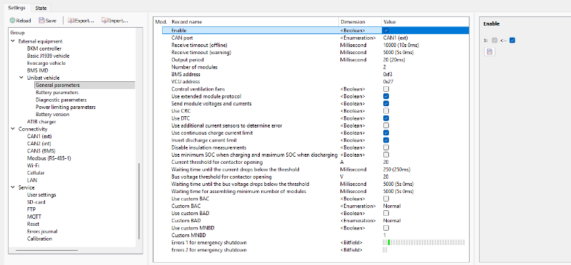
A description of "Unibat vehicle" protocol is provided by request to electric@movicom.com.
Trolleybat vehicle
To change communication parameters with vehicle with Trolleybat battery installed, select the "External equipment → Trolleybat vehicle" section:

A description of "Trolleybat vehicle" protocol is provided by request to electric@movicom.com.
ATIB charger
To change the parameters of communication with an ATIB Elettronica charger, select the "External equipment → ATIB charger" section:
In this section:
- Enable – a flag to enable communication with the charger;
- CAN port – port which is used to communicate with the charger:
- CAN1 (ext);
- CAN2 (int);
- Receive timeout – a timeout for receiving packets from the charger (if there is no data being received from the charger for a given time, the connection loss flag is set), millisecond;
- Output period - a period of sending commands to the charger, millisecond;
- Charging voltage – maximum charging voltage, V;
- Set “Charger connected” signal if the charger is online – a flag to generate the “Charger connected” signal if connection with the charger is established.
ESS Modbus controller
To change the parameters of communication with an ESS Modbus controller, select the "External equipment → ESS Modbus controller" section:

In this section:
- Enable – a flag to enable communication with the charger;
- Receive timeout – a timeout for receiving packets from the controller, millisecond;
- Minimum number of modules allowed to charge;
- Minimum number of modules allowed to discharge;
- Ignore heartbeat message in service mode.