3.2 Inputs and outputs
Configuration
Inputs and outputs
Discrete inputs
The BMS Main 2RX device has 4 discrete inputs that detect signal line closing to the virtual ground.
The BMS Main 3X device has 6 discrete inputs that detect signal line closing to the virtual ground, and 2 inputs that detect 9-32V input voltage.
For each discrete input, its assignment and inversion flag are set.
Also, BMS Main 3X has two additional configurable inputs named “KEYRUN” and “CHARGE_ON”, each serves 9-32V input voltage. Those inputs serve as power buttons with additional functions that can be set.
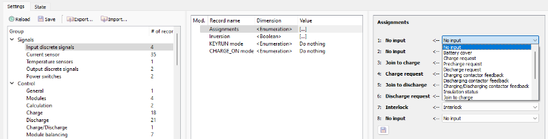
Assignments of discrete inputs are configured in the "Signals → Input discrete signals → Assignments" section:
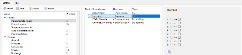
Inversion flags for discrete inputs are configured in the "Signals → Input discrete signals → Inversion" section:
The behavior of “KEYRUN” signal can be configured in the "Signals → Input discrete signals → KEYRUN mode" section:

The behavior of “CHARGE_ON” signal can be configured in the "Signals → Input discrete signals → CHARGE_ON mode" section:

In both “KEYRUN mode” and “CHARGE_ON mode” sections:
- Do nothing – power on device and do nothing;
- Set “Join to discharge” – power on device and set “Join to discharge” signal immediately;
- Set “Join to charge” – power on device and set “Join to charge” signal immediately;
- Set “Discharge request” – power on device and set “Discharge request” signal immediately;
- Set “Charge request” – power on device and set “Charge request” signal immediately.
Current sensor
The BMS Main 2RX device has an ability to measure battery current by 2 external Hall-Effect current sensors.
The BMS Main 3X device has an ability to measure battery current by 3 external Hall-Effect current sensors.
Current sensor settings are configured in the "Signals → Current sensor" section:
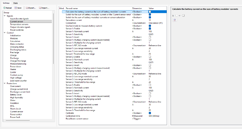
The device supports the following current sensor settings:
- Calculate the battery current as the sum of battery modules currents – a flag that determines overall current as sum of battery modules currents (if flag is not set, device uses measurements from a physical current sensor);
- Switch to the sum of battery modules' current on the 'Current sensor error' – a flag that determines overall current as sum of battery modules currents when "Current sensor error" occurs;
- Switch to the sum of battery modules' current on current sensor saturation – a flag that determines overall current as sum of battery modules currents when current sensor is saturated;
- Saturation current – a saturation current, A;
- Connection – type of multiple sensors connection
- One sensor (#1) – only first sensor is used to measure the battery current;
- Two sensors (#1 and #2) in parallel – sensors are connected in parallel (the total battery current equals the sum of two sensors);
- Two sensors (#1 and #2) in different branches – sensors located in two halves of the battery (used in batteries with a middle point);
- Use fast mode to measure battery current – a flag to enable faster current measurement;
- Sensor 1, 2, 3: Enable – a flag to enable the first, second of third current sensor;
- Sensor 1, 2, 3: Nominal current – rated current Inom of the sensor according to the datasheet, A;
- Sensor 1, 2, 3: Sensitivity – sensitivity of the current sensor according to the datasheet, V / Inom.;
- Sensor 1, 2, 3: Invert – invert the sign of the measured value;
- Sensor 1, 2, 3: Multiply charging current (experimental) – an experimental flag for scaling the charging current by given multiplier;
- Sensor 1, 2, 3: Multiplier for charging current – charging current multiplier;
- Sensor 1, 2, 3: REF_IN2 mode – mode of additional analog line:
- Not connected;
- Reference line – reference output of the sensor;
- Low range (for the dual range sensor) - a second output of a dual-range sensor (for example, LEM DHAB series);
- Sensor 1, 2, 3: Low range nominal current - rated current Inom of the low current line of dual range sensor according to the datasheet, A;
- Sensor 1, 2, 3: Low range sensitivity – sensitivity of the low current line of dual range sensor according to the datasheet, V / Inominal.;
- Sensor 1, 2, 3: Threshold for low range – a threshold current value at which the device uses the readings of the high current sensor instead of low current, A;
- Calibrate – a flag to calibrate (find a 0A point) the current sensor when the device is started;
- Calibration time – calibration time of the current sensor, millisecond;
- Recalibrate current sensor – a command to calibrate the current sensor manually.
Temperature sensors
Temperature sensors settings are configured in the "Signals → Temperature sensors" section:

In this section:
- Type – a type of temperature sensors.
External 1-2 signals
External signals are the signals that can be generated depending on other internal signals.
To change the conditions of External 1-2 signals generation, open the "Signals → External 1-2 signals" section:
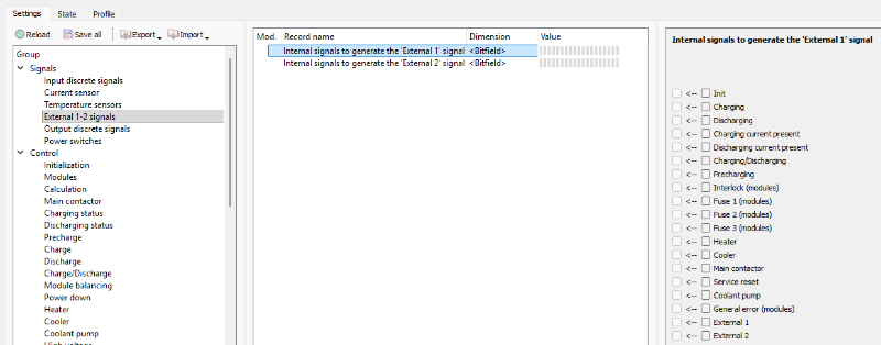 In this section:
- Internal signals to generate the 'External 1' signal – a bitfield to choose the internal signals which will generate External 1 signal;
- Internal signals to generate the 'External 2' signal – a bitfield to choose the internal signals which will generate External 2 signal.
Output discrete signals
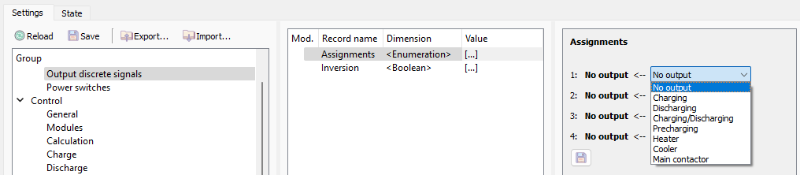
The BMS Main 2RX and BMS Main 3X devices have 4 open drain type outputs.
For each discrete output, its assignment and inversion flag are set.
Assignments of discrete outputs are configured in the "Signals → Output discrete signals → Assignments" section:
Inversion flags for discrete outputs are configured in the "Signals → Output discrete signals → Inversion" section:

Power switches
The BMS Main 2RX device has 4 power relays to drive contactors.
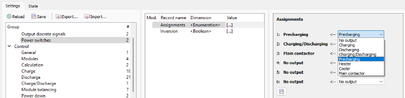
The BMS Main 3X device has 6 power switches to drive contactors.
For each switch, its assignment and inversion flag are set.
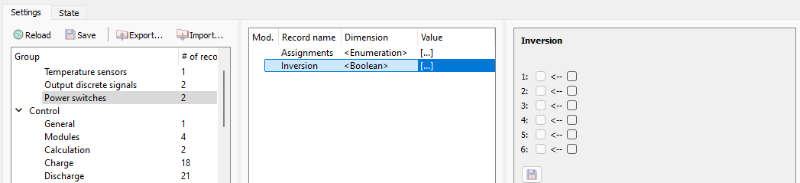
Assignments of power switches are configured in the "Signals → Power switches → Assignments" section:
Inversion flags for switches are configured in the “Signals → Power switches → Inversion” section: