

3.7 External equipment
Configuration
External equipment
The BMS Main 2.x can communicate with chargers, inverters, display panels, forklifts, etc.
J1939 charger
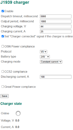
To change the parameters of communication with the charger using J1939 protocol, select the menu "External equipment → J1939 charger":
In this section:
- Settings:
- Enable – a flag to enable communication with the charger;
- Dispatch timeout – a timeout of the dispatching of packets from the charger (if there is no data being received from the charger for a given time, the connection loss flag is set), millisecond;
- Output period – a period of sending commands to the charger, millisecond;
- Charging voltage – maximum charging voltage, V;
- Charging current – maximum charging current, А;
- Set “Charger connected” signal if the charger is online – a flag to generate the “Charger connected” signal if connection with the charger is established;
- OSN Power compliance – a flag to enable compatibility mode with chargers by OSN Power;
- Protocol – choose the protocol version;
- V0;
- V1;
- Battery type – a type of the battery (for OSN Power chargers);
- Charging mode (for OSN Power chargers);
- CCS2 compliance – a flag to enable compatibility mode with the new generation of stationary chargers;
- Discharging current – maximum discharging current, A (for CCS2 chargers);
- Great Power compliance – a flag to enable compatibility mode with the Great Power chargers.
- Charger state:
- Online – (No – no connection with the charger; Yes – connection with the charger is established);
- Voltage – a value of voltage received from the charger, V;
- Current – a value of current received from the charger, А.
Algorithm for working with the charger:
BMS sends a command to charge the battery if the "Allow charging" flag is set (see Charging control).
Eltek charger
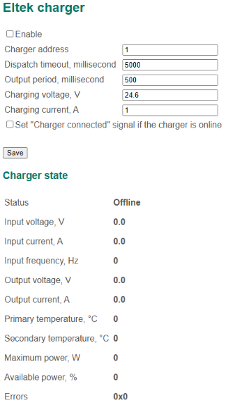
To change the communication parameters with Eltek chargers, select the menu "External equipment → Eltek charger":
In this section:
- Settings:
- Enable – a flag to enable communication with the charger;
- Charger address – the charger’s network address;
- Dispatch timeout – a timeout of the dispatching of packets from the charger (if no data is being received from the charger during this time, the connection loss flag is set), millisecond;
- Output period – a period of sending commands to the charger, millisecond;
- Charging voltage – maximum charging voltage, V;
- Charging current – maximum charging current, А;
- Set “Charger connected” signal if the charger is online – a flag to generate the “Charger connected” signal if connection with the charger is established;
- Charger state:
- Status – (Offline – no connection with charger; No charge; Charge; Recoverable error; Nonrecoverable error);
- Input voltage, V;
- Input current, А;
- Input frequency, Hz;
- Output voltage, V;
- Output current, А;
- Primary temperature – temperature measured by the main temperature sensor, °C;
- Secondary temperature – temperature measured by an additional temperature sensor, °C;
- Max power – maximum power that the charger can provide, W;
- Available power, %;
- Errors – hexadecimal word with charger errors.
Algorithm for working with the charger:
BMS sends a command to charge the battery if the "Allow charging" flag is set (see Charging control).
MicroPower charger
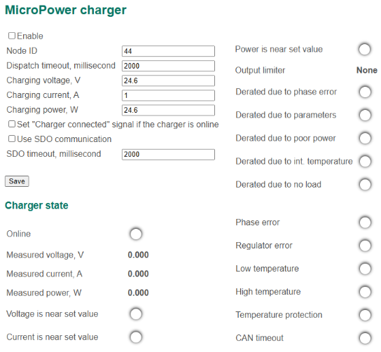
To change the parameters of communication with the MicroPower charger, select the menu "External equipment → MicroPower charger":
In this section:
- Settings:
- Enable – a flag to enable communication with the charger;
- Node ID – charger identifier in the CANopen network;
- Dispatch timeout – a timeout of the dispatching of packets from the charger (if there is no data being received from the charger for a given time, the connection loss flag is set), millisecond;
- Charging voltage – maximum charging voltage, V;
- Charging current – maximum charging current, A;
- Charging power – maximum charging power, W;
- Set “Charger connected” signal if the charger is online – a flag to generate the “Charger connected” signal if connection with the charger is established;
- Charger state:
- Online – a flag of normal communication with the charger;
- Measured voltage;
- Measured current;
- Measured power;
- Voltage is near set value – output voltage of the charger is close to the required value;
- Current is near set value – output current of the charger is close to the required value;
- Power is near set value – output power of the charger is close to the required value;
- Output limiter:
- None;
- Voltage;
- Current;
- Power;
- Int. temperature – output is limited due to internal charger temperature;
- Volt. boundary – bound voltage is reached;
- Curr. boundary – bound current is reached;
- Pow. boundary – bound power is reached;
- DC limit;
- AC limit;
- Pow. AC limit – input power limitation;
- Phase error;
- Derated due to phase error;
- Derated due to parameters;
- Derated due to poor power;
- Derated due to int. temperature;
- Derated due to no load;
- Phase error;
- Regulator error;
- Low temperature;
- High temperature;
- Temperature protection;
- CAN timeout.
Algorithm for working with the charger:
BMS sends a command to charge the battery if the "Allow charging" flag is set (see Charging control).
SPE charger
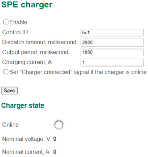
To change the parameters of communication with the S.P.E. charger, select the menu "External equipment → SPE charger":
In this section:
- Settings:
- Enable – a flag to enable communication with the charger;
- Control ID – control message identifier setting the charging current;
- Dispatch timeout – a timeout of the dispatching of packets from the charger (if there is no data being received from the charger for a given time, the connection loss flag is set), millisecond;
- Charging current – maximum charging current, A;
- Set “Charger connected” signal if the charger is online – a flag to generate the “Charger connected” signal if connection with the charger is established;
- Charger state:
- Online – a flag of normal communication with the charger;
- Nominal voltage;
- Nominal current.
Algorithm for working with the charger:
BMS sends a command to charge the battery if the "Allow charging" flag is set (see Charging control).
Bassi charger
To change the parameters of communication with the Bassi charger, select the menu "External equipment → Bassi charger":
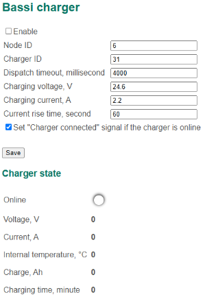
In this section:
- Settings:
- Enable – a flag to enable communication with the charger;
- Node ID – BMS identifier in the CANopen network;
- Charger ID – charger identifier in the CANopen network;
- Dispatch timeout – a timeout of the dispatching of packets from the charger (if there is no data being received from the charger for a given time, the connection loss flag is set), millisecond;
- Charging voltage – maximum charging voltage, V;
- Charging current – maximum charging current, A (as an alternative it is possible to use charge current limit calculated in the section "Cells → Charge current map");
- Current rise time – a time of the gradual increasing the charging current to the maximum value, second;
- Set "Charger connected" signal when the charger is online.
- Charger state:
- Online – a flag of normal communication with the charger;
- Voltage – voltage measured by the charger, V;
- Current – current measured by the charger, A;
- Internal temperature – temperature of the charger, °C;
- Charge – energy which the charger transferred to the battery, Ah;
- Charging time – duration of the battery charging, minute.
Algorithm for working with the charger:
BMS sends a command to charge the battery if the "Allow charging" flag is set (see Charging control).
ATIB Elettronica charger
To change the parameters of communication with the ATIB Elettronica charger, select the menu "External equipment → ATIB Elettronica charger":
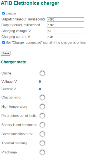
In this section:
- Settings:
- Enable – a flag to enable communication with the charger;
- Dispatch timeout – a timeout of the dispatching of packets from the charger (if there is no data being received from the charger for a given time, the connection loss flag is set), millisecond;
- Charging voltage – maximum charging voltage, V;
- Charging current – maximum charging current, A;
- Set "Charger connected" signal when the charger is online.
- Charger state:
- Online – a flag of normal communication with the charger;
- Voltage – voltage measured by the charger, V;
- Current – current measured by the charger, A;
- Charger error;
- High temperature;
- Parameters out of limits;
- Battery is not connected;
- Communication error;
- Thermal derating;
- Precharge.
Algorithm for working with the charger:
The BMS sends a command to charge the battery if the "Allow charging" flag is set (see Charging control).
Fronius charger
To change the parameters of communication with the Fronius charger, select the menu "External equipment → Fronius charger":
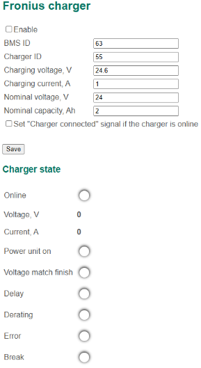
In this section:
- Settings:
- Enable – a flag to enable communication with the charger;
- BMS ID –BMS Main 2.x identificator in CANopen network;
- Charger ID – Fronius charger identificator in CANopen network;
- Charging voltage – maximum charging voltage, V;
- Charging current – maximum charging current, A;
- Nominal voltage – nominal battery voltage, V;
- Nominal capacity – nominal battery capacity, A;
- Set "Charger connected" signal when the charger is online.
- Charger state:
- Online – a flag of normal communication with the charger;
- Voltage – voltage measured by the charger, V;
- Current – current measured by the charger, A;
- Power unit on – charger power status;
- Voltage match finish – charging finished due to voltage achievement;
- Delay;
- Derating;
- Error – charger error;
- Break – charging stopped;
Algorithm for working with the charger:
The BMS sends a command to charge the battery if the "Allow charging" flag is set (see Charging control).
Webasto charger
To change the parameters of communication with the Webasto charger, select the menu "External equipment → Webasto charger":
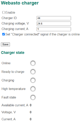
In this section:
- Settings:
- Enable – a flag to enable communication with the charger;
- Charger ID – Fronius charger identificator in CANopen network;
- Charging voltage – maximum charging voltage, V;
- Charging current – maximum charging current, A;
- Set "Charger connected" signal when the charger is online.
- Charger state:
- Online – a flag of normal communication with the charger;
- Ready to charge;
- Charging – battery is charging;
- High temperature – charger is overheated;
- Fault state – charger error;
- Available current – maximum allowable charging current, A;
- Voltage – voltage measured by the charger, V;
- Current – current measured by the charger, A;
Algorithm for working with the charger:
The BMS sends a command to charge the battery if the "Allow charging" flag is set (see Charging control).
Skytronic charger
To change the parameters of communication with the Skytronic charger, select the menu "External equipment → Skytronic charger":
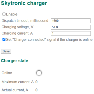
In this section:
- Settings:
- Enable – a flag to enable communication with the charger;
- Dispatch timeout – a timeout of the dispatching of packets from the charger (if there is no data being received from the charger for a given time, the connection loss flag is set), millisecond;
- Charging voltage – maximum charging voltage, V;
- Charging current – maximum charging current, A;
- Set "Charger connected" signal when the charger is online.
- Charger state:
- Online – a flag of normal communication with the charger;
- Maximum current – maximum allowable charging current, A;
- Actual current – current measured by the charger, A.
Algorithm for working with the charger:
The BMS sends a command to charge the battery if the "Allow charging" flag is set (see Charging control).
CCS Fast charge controller
To change the parameters of communication with a CCS Fast charge controller, select the "External equipment → CCS Fast charge controller" section:
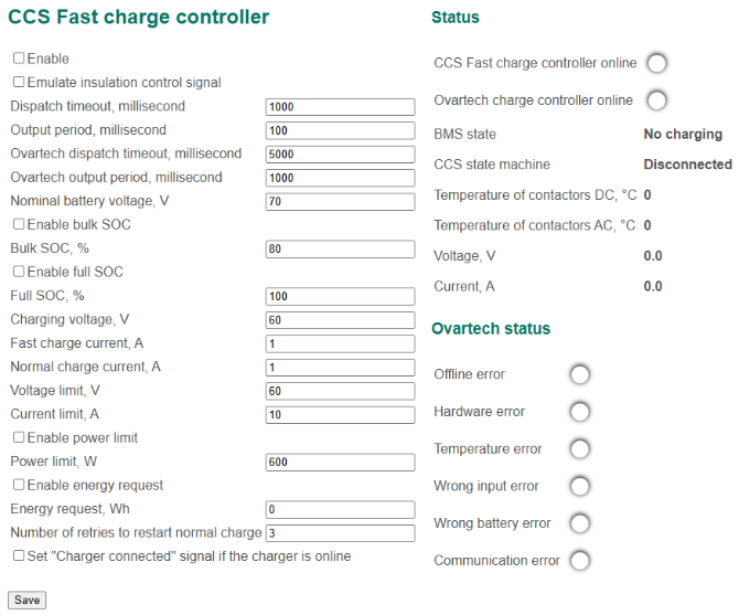
In this section:
- Enable – a flag to enable communication with the charger;
- Emulate insulation control signal – enable emulation of insulation monitoring device signal;
- Receive timeout – a timeout for receiving packets from the charger (if there is no data being received from the charger for a given time, the connection loss flag is set), millisecond;
- Output period – period of transmitting messages to a controller, millisecond;
- Ovartech receive timeout – timeout of receiving messages from charger (if there is no data being received from the charger for a given time, the connection loss flag is set), millisecond;
- Ovartech output period – period of transmitting messages to a charger, millisecond;
- Nominal battery voltage, V;
- Enable bulk SOC – a flag to enable transmitting of partial charge SOC from BMS to controller;
- Bulk SOC – partial charge SOC value, %;
- Enable full SOC – a flag to enable transmitting of full charge SOC from BMS to controller;
- Full SOC – full charge SOC value, %;
- Charge voltage, V;
- Fast charge current, A;
- Nominal charge current, A;
- Voltage limit – maximum allowable battery voltage, V;
- Current limit – maximum allowable battery current, A;
- Enable power limit – a flag to enable transmitting of maximum allowable charge power from BMS to controller;
- Power limit – maximum allowable charge power value, W;
- Enable energy request – a flag to enable request for battery energy from BMS to controller;
- Energy request – battery energy value, Wh;
- Number of retries to restart nominal charge – number of retries to restart nominal charge after connection loss with charger;
- Set “Charger connected” signal if the charger is online – a flag to generate the “Charger connected” signal if connection with the charger is established.
Resonant Link charger
To change the communication parameters with the Resonant Link charger, select the menu "External equipment → Resonant Link charger":

In this section: TBA
Sunny Island inverter
To change the communication parameters with the SMA Sunny Island inverter, select the menu "External equipment → Sunny Island inverter":
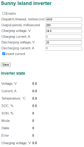
In this section:
- Settings:
- Enable – a flag to enable communication with the inverter;
- Dispatch timeout – a timeout of the dispatching of packets from the inverter (if no data is being received from the inverter during this time, the connection loss flag is set), millisecond;
- Output period – a period of sending commands to the inverter, millisecond;
- Charging voltage, V – maximum charging voltage, V;
- Charging current, А – maximum charging current, A;
- Discharging voltage – maximum discharging voltage, V;
- Discharging current – maximum discharging current, А;
- Invert current – a flag to inverse current sending to the inverter;
- Inverter state:
- Voltage – inverter input voltage, V;
- Current – inverter input current, А;
- Temperature – temperature of the inverter, °C;
- SOC – battery state of charge, %;
- SOH – battery state of health, %;
- Mode – inverter function code;
- State – inverter status code;
- Error – inverter error code;
- Charge voltage, V.
When working with the Sunny Island inverter, the BMS Main 2.x board sends the packets with the values of voltage and charge/discharge current continuously with the period “Output period”: Charging voltage, Charging current, Discharging voltage, Discharging current.
Pylontech inverter
To change the parameters of communication with a Pylontech inverter, select the "External equipment → Pylontech inverter" section:
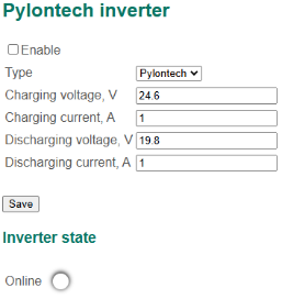
In this section:
- Enable – a flag to enable communication with the inverter;
- Type – invertor type:
- Pylontech;
- Solis;
- Charge voltage, V – maximum charging voltage, V;
- Charge current, А – maximum charging current, A;
- Discharge voltage (min) – minimum discharging voltage, V;
- Discharge current – maximum discharging current, А.
Battery cycling
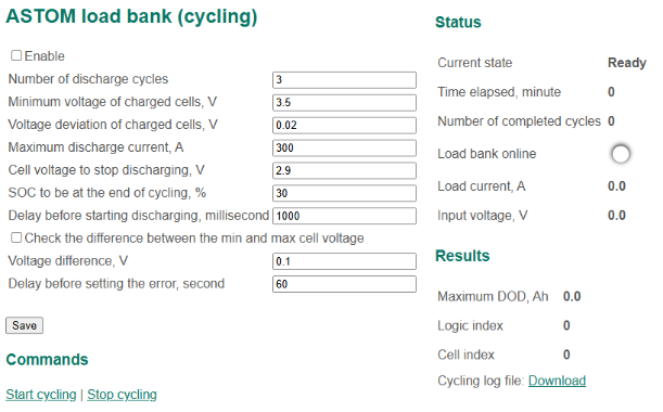
To change the parameters of communication with a ASTOM or XD Discharger load banks, select the "External equipment → Battery cycling" section:
In this section:
- Enable – a flag to enable communication with the bank;
- Type of the load:
- ASTOM;
- XD Discharger;
- Number of discharge cycles;
- Minimum voltage of charged cells, V;
- Voltage deviation of charged cells – minimum allowable deviation of the cells voltage at which battery states as charged, V;
- Maximum discharge current, A;
- Cell voltage to stop discharging, V;
- SOC to be at the end of cycling – target SOC at the end of charge-discharge cycling, V;
- Delay before starting discharging – a delay before transmitting command to the load to start discharging, millisecond;
- Check the difference between the min and max cell voltage – a flag to enable check of difference between the minimum and maximum cell voltages to generate an error;
- Voltage difference – difference between the minimum and maximum cell voltages for error to be generated and cycling to be stopped, V;
- Delay before setting the error – a delay before generating an error, second.
XD Discharger (cycling)
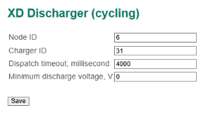
To change the additional parameters of communication with a XD Discharger load banks, select the "External equipment → XD Discharger (cycling)" section:
In this section:
- Node ID – BMS identificator in CANopen network;
- Charger ID – charger identificator in CANopen network;
- Dispatch timeout – a timeout of the dispatching of packets from the storage (if no data is being received from the inverter during this time, the connection loss flag is set), millisecond;
- Minimum discharge voltage, V.
Bassi storage
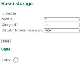
To change communication parameters with Bassi storage, select the menu "External equipment → Bassi storage":
In this section:
- Settings:
- Enable – a flag to enable communication with the charger;
- Charger ID – charger identificator in CANopen network;
- Dispatch timeout – a timeout of the dispatching of packets from the storage (if no data is being received from the inverter during this time, the connection loss flag is set), millisecond;
- Charger state:
- Online – a flag of normal communication with the storage;
HYG Class I-III truck
HYG Class I-III equipment is installed on the forklifts by the group of companies HYSTER-YALE.
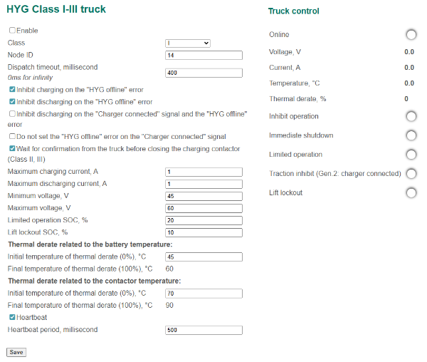
To change communication parameters with HYG Class I-III equipment, select the menu "External equipment → HYG Class I-III truck":
 In this section:
- Settings:
- Enable – a flag to enable communication with the forklift;
- Class – a class of equipment (I or II, III or I, II, III Gen.2);
- Node ID – an equipment identifier in the CANopen network;
- Dispatch timeout – a timeout of the dispatching of packets from the forklift (if no data is being received from the forklift during this time, the “HYG offline“ flag is set), millisecond; at a value of 0 milliseconds, the "HYG offline" error does not occur;
- Inhibit charging on the "HYG offline" error – a flag to forbid charging if the "HYG offline" error is generated;
- Inhibit discharging on the "HYG offline" error – a flag to forbid discharging if the "HYG offline" error is generated;
- Inhibit discharging on the “Charger connected” signal and the "HYG offline" error – a flag to forbid discharging if the “Charger connected” signal presents and "HYG offline" error is generated;
- Do not set the "HYG offline" error on the "Charger connected" signal – a flag to prevent the "HYG offline" error from occurring if the "Charger connected" signal is set;
- Wait for confirmation from the truck before closing the charging contactor (Class II, III) – a flag that controls whether to wait for confirmation from the HYG truck or not, to allow the battery to be charged;
- Maximum charge current, А;
- Maximum discharge current, А;
- Minimum voltage, V;
- Maximum voltage, V;
- Limited operation SOC – SOC level, at which the forklift goes into a state of limited functionality, %;
- Lift lockout SOC – SOC level, at which the forklift locks the lift, %;
- Thermal derate related to the battery temperature (Gen.2 class):
- Initial temperature of thermal derate (0%) – a value of the battery temperature at which the thermal derate starts;
- Final temperature of thermal derate (100%) – a value of the battery temperature at which the thermal derate ends and the forklift performance is fully limited (the maximum temperature from the "Protections → High temperature protection" section);
- Thermal derate related to the contactor temperature (Gen.2 class):
- Initial temperature of thermal derate (0%) – a value of the contactor temperature at which the thermal derate starts;
- Final temperature of thermal derate (100%) – a value of the contactor temperature at which the thermal derate ends and the forklift performance is fully limited (the maximum temperature from the "Protections → Contactor high temperature protection" section);
- Heartbeat – a flag to enable generation of the Heartbeat messages to the forklift;
- Heartbeat period – Heartbeat sending period, millisecond;
- Truck control – the communication state and control commands transferred to the forklift:
- Online – a flag of normal communication with the forklift;
- Voltage, V;
- Current, А;
- Temperature, °C;
- Thermal derate, %;
- Inhibit operation;
- Immediate shutdown;
- Limited operation – mode of limited functionality (it is formed if the battery SOC is less than the “Limited operation SOC” value);
- Traction inhibit (Gen.2: charger connected);
- Lift lockout – blocking of the lift (it is formed if the battery SOC is less than the “Lift lockout SOC” value).
The board with the identifier “Node ID” continuously transmits to the forklift the control commands with a period of 100 milliseconds.
Combilift truck
To change communication parameters with a Combilift forklift, select the menu "External equipment → Combilift truck":
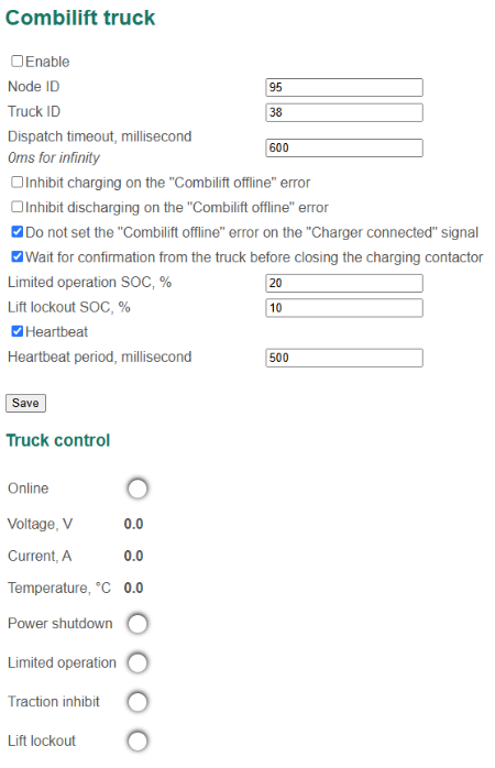
In this section:
- Settings:
- Enable – a flag to enable communication with the forklift;
- Node ID – BMS Main identifier in the CANopen network;
- Truck ID – forklift identifier in the CANopen network;
- Dispatch timeout – a timeout of the dispatching of packets from the forklift (if no data is being received from the forklift during this time, the “Combilift offline“ flag is set), millisecond; at a value of 0 milliseconds, the "Combilift offline" error does not occur;
- Inhibit charging on the "Combilift offline" error – a flag to forbid charging if the "Combilift offline" error is generated;
- Inhibit discharging on "Combilift offline" error – a flag to forbid discharging if the "Combilift offline" error is generated;
- Do not set the "Combilift offline" error on the "Charger connected" signal;
- Wait for confirmation from the truck before closing the charging contactor;
- Limited operation SOC – SOC level, at which the forklift goes into a state of limited functionality, %;
- Lift lockout SOC – SOC level, at which the forklift locks the lift, %;
- Heartbeat – a flag to enable generation of the Heartbeat messages to forklift;
- Heartbeat period – Heartbeat sending period, millisecond;
- Truck control – the communication state and control commands transferred to the forklift:
- Online – a flag of normal communication with equipment;
- Voltage, V;
- Current, А;
- Temperature, °C;
- Power shutdown – turn off the forklift power;
- Limited operation – mode of limited functionality (it is formed if the battery SOC is less than the “Limited operation SOC” value);
- Traction inhibit;
- Lift lockout – blocking of the lift (it is formed if the battery SOC is less than the “Lift lockout SOC” value).
The board with the identifier “Node ID” continuously transmits to the forklift the control commands with a period of 200 milliseconds.
Spirit AGV truck
To change communication parameters with Spirit AeroSystems truck, select the menu "External equipment → Spirit AGV truck":
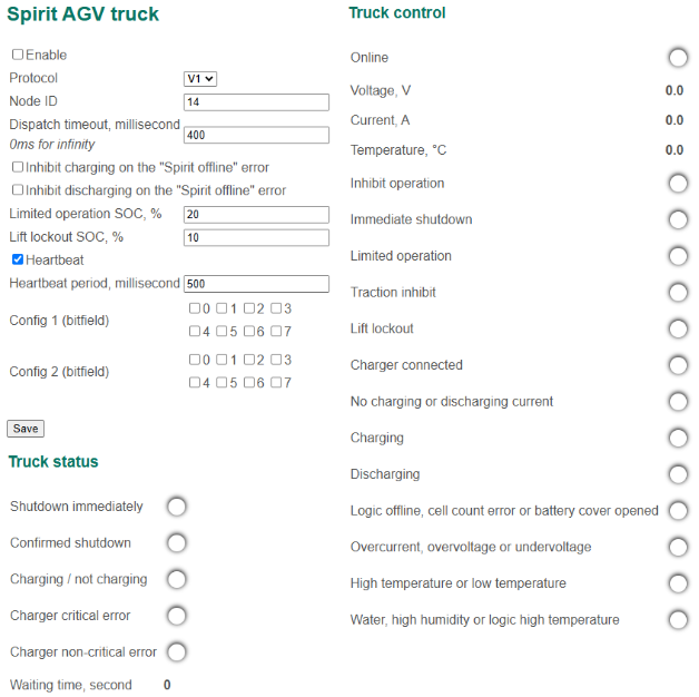
In this section:
- Settings:
- Enable – a flag to enable communication with the truck;
- Protocol – version of protocol:
- V1;
- V2;
- Node ID – BMS Main identifier in the CANopen network;
- Dispatch timeout – a timeout of the dispatching of packets from the truck (if no data is being received from the truck during this time, the “Spirit offline“ flag is set), millisecond; at a value of 0 milliseconds, the "Spirit offline" error does not occur;
- Inhibit charging on the "Spirit offline" error – a flag to forbid charging if the "Spirit offline" error is generated;
- Inhibit discharging on the "Spirit offline" error – a flag to forbid discharging if the "Spirit offline" error is generated;
- Limited operation SOC – SOC level, at which the truck goes into a state of limited functionality, %;
- Lift lockout SOC – SOC level, at which the truck locks the lift, %;
- Heartbeat – a flag to enable generation of the Heartbeat messages to the truck;
- Heartbeat period – Heartbeat sending period, millisecond;
- Config 1 (bitfield), Config 2 (bitfield) – configuration bitfields;
- Truck control – the communication state and control commands transferred to the truck:
- Online – a flag of normal communication with the truck;
- Voltage,V;
- Current, A;
- Temperature, °C;
- Inhibit operation;
- Immediate shutdown;
- Limited operation – mode of limited functionality (it is formed if the battery SOC is less than the “Limited operation SOC” value);
- Traction inhibit;
- Lift lockout – blocking of the lift (it is formed if the battery SOC is less than the “Lift lockout SOC” value).
- Charger connected;
- No charging or discharging current;
- Charging;
- Discharging;
- Logic offline, cell count error or battery cover opened;
- Overcurrent, overvoltage or undervoltage;
- High temperature or low temperature;
- Water, high humidity or logic high temperature.
- Truck status – forklift status sent to BMS:
- Shutdown immediately;
- Confirmed shutdown;
- Charging / not charging;
- Charger critical error;
- Charger non-critical error;
- Waiting time, s.
The board with the identifier “Node ID” continuously transmits to the truck the control commands with a period of 100 milliseconds.
Crown truck
The BMS Main 2.x board uses the BMS Crown adapter to control powering the Crown forklift.
To change communication parameters with the BMS Crown adapter, select the menu "External equipment → Crown truck":
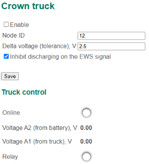
In this section:
- Settings:
- Enable – a flag to enable communication with the BMS Crown;
- Node ID – BMS Crown identifier in the CANopen network;
- Delta voltage (tolerance) – a maximum deviation between the battery voltage and the voltage output by the Crown forklift system, V;
- Inhibit discharging on EWS signal – a flag to inhibit reclosing the discharging contactor after sending EWS signal to the forklift;
- Truck control – the communication state and control commands transferred to the forklift:
- Online – communication status with the BMS Crown adapter;
- Voltage A2 (from battery) – voltage measured by the BMS Crown on battery, V;
- Voltage A1 (from truck) – voltage produced by the Crown forklift system, V;
- Relay – command to power on the Crown forklift.
When working with the Crown forklift, the algorithm for controlling the discharging relay is changed. The state machine used to switch the discharging relay is described below.
1) "Discharging off" state.
In this state, the discharging relay is open.
If all the conditions are met:
- the charger is disconnected;
- the charging relay is open;
- the “Critical error” is cleared;
- the "Undervoltage" error is cleared;
- the "Overcurrent" error is cleared;
- the "High temperature" error is cleared.
then the transition to the state "Load connection".
2) “Load connection” state.
In this state, the discharging relay is still open and at the same time the battery voltage is switched to line A2 (see “Relay” status field).
If, after T = 10 seconds, the difference is |Voltage A2-Voltage A1| < “Delta voltage (tolerance)”, then the transition to the state "Load connected". If after the expiration of the time T the difference |Voltage A2-Voltage A1| > “Delta voltage (tolerance)”, then the transition to the "Crown error".
3) "Load connected" state.
In this state, the discharging relay is closed.
If one of the conditions:
- the charger is connected;
- the “Critical error” is generated;
- the "Undervoltage" error is generated;
- the "Overcurrent" error is generated;
- the "High temperature" error is generated;
- Voltage A1 = 0V (load disconnection initiated by the forklift)
then the transition to the "Discharging Off" state is performed.
4) “Load disconnection” state.
In this state, the discharging relay is still closed and at the same time the battery voltage is not output to the A2 line.
After T = 10 seconds, the transition to the "Load Off" state if performed.
5) "Crown error" state.
In this state, the discharging relay is open and the "Crown error" is generated. If the "Inhibit discharging on EWS signal" is not set, then after T = 10 seconds, the "Crown error" is cleared and the transition to the "Discharging Off" state is performed.
The value of T is set in the "Delay before starting the discharge" field (see Discharging control).
ZiK truck
To change communication parameters with ZiK truck, select the menu "External equipment → ZiK truck":
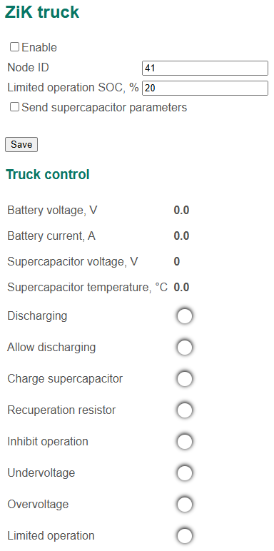
In this section:
- Settings:
- Enable – a flag to enable communication with the ZiK truck;
- Node ID – ZiK identifier in the CANopen network;
- Limited operation SOC – SOC level at which the truck goes to limited operation mode, %;
- Send supercapacitor parameters – a flag to enable transmitting the supercapacitor parameters.
- Truck control – the communication state and control commands transferred to the truck:
- Battery voltage, V;
- Battery current, A;
- Supercapacitor voltage, V;
- Supercapacitor temperature, °C;
- Discharging;
- Allow discharging;
- Charge supercapacitor;
- Recuperation resistor;
- Inhibit operation;
- Undervoltage;
- Overcurrent;
- Limited operation;
The BMS with the identifier “Node ID” continuously transmits to the truck the control commands with a period of 100 milliseconds.
Evocargo Evo1.1 truck
To change communication parameters with an Evocargo Evo1.1 truck, select the "External equipment → Evocargo Evo1.1 truck" section:
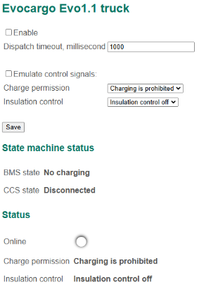
In this section:
- Enable – a flag to enable communication with the truck;
- Receive timeout – a timeout for receiving packets from the truck, millisecond.
UPS
To change communication parameters with uninterruptible power supply, select the menu "External equipment → UPS":
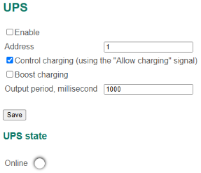
In this section:
- Settings:
- Enable – a flag to enable communication with the UPS;
- Address – a UPS address in Modbus network;
- Control charging (using "Allow charging signal") – a flag that allows the BMS Main 2.x board to control the battery charging process; if this flag is not set, the board prohibits the UPS from charging the battery;
- Boost charging – a flag to enable battery fast charging;
- Output period – a commands sending period, millisecond;
- State:
- Online – a flag of normal communication with the UPS.
The BMS Main 2.x board communicates with the UPS via RS-485 bus (Modbus RTU protocol). When the UPS module is turned on (the "Enable" flag is set), the board starts sending control packets, in which a command is sent to turn on and off the charger (in accordance with the signal state "Allow charging signal").
BKM trolleybus
To change communication parameters with BKM trolleybus equipment, select the menu "External equipment → BKM trolleybus":
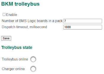
In this section:
- Settings:
- Enable – a flag to enable communication with the trolleybus;
- Number of BMS Logic boards in a pack – a number of the BMS Logic boards per battery module;
- Dispatch timeout – a timeout of the dispatching of packets from the trolleybus equipment (if no data is being received from the trolleybus equipment during this time, the “Trolleybus online” и “Charger online” flags are cleared), millisecond;
- Trolleybus state – the communication state with the trolleybus equipment:
- Trolleybus online – a flag of normal communication with the trolleybus;
- Charger online – a flag of normal communication with the charger.
Basic J1939 vehicle
To change communication parameters with a vehicle by J1939 protocol, select the menu "External equipment → Basic J1939 vehicle":
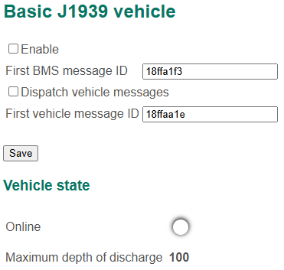
In this section:
- Settings:
- Enable – a flag to enable communication with the vehicle;
- First BMS message ID;
- Dispatch vehicle messages – a flag to activate vehicle messages dispatch;
- First vehicle message ID;
- Vehicle state:
- Online – a flag of normal communication with the vehicle;
- Maximum depth of discharge – maximum allowed DOD of the battery.
Bender iso165C device
To change communication parameters with a Bender iso165C, select the "External equipment → Bender iso165C device" section:
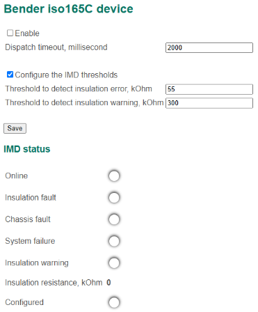
In this section:
- Enable – a flag to enable communication with the IMD;
- Receive timeout – a timeout for receiving packets from the IMD, millisecond;
- Configure the IMD thresholds – a flag to enable the threshold values for generating insulation error and insulation warning;
- Threshold to detect insulation error – threshold resistance value to generate the insulation error, Ohm;
- Threshold to detect insulation warning – threshold resistance value to generate the insulation warning, Ohm.
Indication board
The BMS Main 2.x board has the ability to configure and update the firmware of the BMS Indication 1.x board.
To go to the configuration interface, select the menu "External equipment → Indication board":
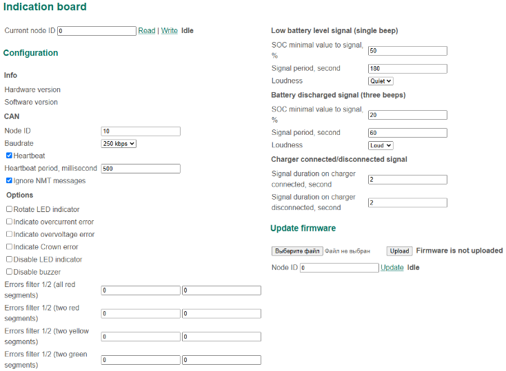
In this section:
- Current node ID – a network address of the BMS Indication board (default 10);
- Hardware version;
- Software version;
- Read – command to read BMS Indication settings;
- Write – command to write BMS Indication settings;
- Process state:
- Idle – no action is performed;
- Reading config – reading the BMS Indication configuration;
- Read done (x%) – reading is done, got x parameters;
- Writing config – writing the BMS Indication configuration;
- Write done (y%) – writing is done, applied y parameters;
- Configuration:
- CAN – CAN bus settings:
- Node ID – new identifier in the CANopen network;
- Baudrate – CAN bus speed;
- Heartbeat – a flag to enable Heartbeat message generation;
- Heartbeat period – Heartbeat generation period, millisecond;
- Ignore NMT messages – a flag to ignore CANopen command messages;
- Options:
- Rotate LED indicator;
- Indicate overcurent error;
- Indicate overvoltage error;
- Indicate Crown error;
- Disable LED indicator;
- Disable buzzer;
- Errors filter (all red segments), Errors filter (two red segments), Errors filter (two yellow segments), Errors filter (two green segments) – filters for errors (hexadecimal representation), which should be notified by indication board (see the “BMS Indication 1.x Connection and configuration manual”);
- Low battery level signal (single beep);
- Battery discharged signal (three beeps):
- SOC minimal value to signal – minimum battery state of charge to issue a warning sound, %;
- Signal period – period of the warning sound, seconds;
- Loudness – volume of the warning sound (Quiet or Loud);
- Charger connected/disconnected signal:
- Signal duration on charger connected, seconds;
- Signal duration on charger disconnected, seconds.
- CAN – CAN bus settings:
- Update firmware – board firmware update:
- The form for uploading the program file to the SD card. Information about the presence of the file with the program on the SD card is shown here:
- Firmware is not uploaded – information that there is no file on the SD card with the program for the indication board;
- Firmware is uploaded – information that there is a file on the SD card with the program for the indication board;
- Node ID – a network address of the indication board whose program will be updated;
- Update – a link that will start the update of the program for the indication board (before clicking, upload the file with the firmware of the indication board to the SD card). Information about the updating process is shown here:
- Starting bootloader – launch of indication board loader;
- Bootloader started – indication board loader is running;
- Bootloader failed – the indication board loader is not running;
- Done – updated successfully;
- Parsing firmware error – error parsing the file with the indication board program;
- No connection – no connection with indication board loader;
- Start programming session error – failed to start indication board programming session;
- Erasing error – program memory erase error;
- Programming data error;
- Stop programming session error.
- The form for uploading the program file to the SD card. Information about the presence of the file with the program on the SD card is shown here:
To configure BMS Indication board follow next steps:
- Enter the board CANopen id in the "Current node ID" field.
- Click the "Read" link to start reading board configuration.
- Check reading result in the "State" field. The message it contains should be equal to "Read done (x%)", where x > 50.
- Change the board settings in the "Configuration" section.
- Click the "Write" link to start writing board configuration.
- Check writing result in the "State" field. The message it contains should be equal "Write done (y%)", where y = x.
- Make the second reading of the configuration (step 2) and check the new settings are saved.
To update BMS Indication board firmware follow next steps:
- Using the form, upload the file with the indication board program to the SD card (the file must be in the format Motorola S-Record, SREC).
- Check that the file with the indication board program is uploaded (press the "External equipment → Indication board" menu again).
- In the “Node ID” field, enter the network address of the indication board and click the “Update” button.
- Periodically monitor the update process – click on the menu "External equipment → Indication board" (update takes about 30 seconds).
Display board
The BMS Main 2.x board has the ability to configure and update the firmware of the BMS Display board.
To go to the configuration interface, select the menu "External equipment → Display board":
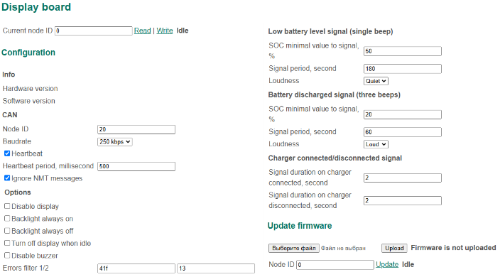
In this section:
- Current node ID – a network address of the BMS Display board (default 10).
- Hardware version;
- Software version;
- Read – command to read BMS Display settings;
- Write – command to write BMS Display settings;
- Process state:
- Idle – no action is performed;
- Reading config – reading the BMS Display configuration;
- Read done (x%) – reading is done, got x parameters;
- Writing config – writing the BMS Display configuration;
- Write done (y%) – writing is done, applied y parameters;
- Configuration:
- CAN – CAN bus settings:
- Node ID – new identifier in the CANopen network;
- Baudrate – CAN bus speed;
- Heartbeat – a flag to enable Heartbeat message generation;
- Heartbeat period – Heartbeat generation period, millisecond;
- Ignore NMT messages – a flag to ignore CANopen command messages;
- Options:
- Disable display;
- Backlight always on;
- Backlight always off;
- Turn off display when idle;
- Disable buzzer;
- Errors filter – a filter for errors (hexadecimal representation), which should be notified by the board (see the “BMS Display 1.x Connection and configuration manual”);
- Low battery level signal (single beep);
- Battery discharged signal (three beeps):
- SOC minimal value to signal – minimum battery state of charge to issue a warning sound, %;
- Signal period – period of the warning sound, seconds;
- Loudness – volume of the warning sound (Quiet or Loud);
- Charger connected/disconnected signal :
- Signal duration on charger connected, seconds;
- Signal duration on charger disconnected, seconds.
- CAN – CAN bus settings:
- Update firmware – board firmware update:
- The form for uploading the program file to the SD card. Information about the presence of the file with the program on the SD card is shown here:
- Firmware is not uploaded – information that there is no file on the SD card with the program for the display board;
- Firmware is uploaded – information that there is a file on the SD card with the program for the display board;
- Node ID – a network address of the display board whose program will be updated;
- Update – a link that will start the update of the program for the display board (before clicking, upload the file with the firmware of the display board to the SD card). Information about the updating process is shown here:
- Starting bootloader – launch of display board loader;
- Bootloader started – display board loader is running;
- Bootloader failed – the display board loader is not running;
- Done – updated successfully;
- Parsing firmware error – error parsing the file with the display board program;
- No connection – no connection with the display board loader;
- Start programming session error – failed to start display board programming session;
- Erasing error – program memory erase error;
- Programming data error;
- Stop programming session error.
- The form for uploading the program file to the SD card. Information about the presence of the file with the program on the SD card is shown here:
To configure the BMS Display board follow the next steps:
- Enter the board CANopen id in the "Current node ID" field.
- Click the "Read" link to start reading board configuration.
- Check reading result in the "State" field. The message it contains should be equal to "Read done (x%)", where x > 50.
- Change the board settings in the "Configuration" section.
- Click the "Write" link to start writing board configuration.
- Check writing result in the "State" field. The message it contains should be equal "Write done (y%)", where y = x.
- Make the second reading of the configuration (step 2) and check the new settings are saved.
To update the BMS Display board firmware follow the next steps:
- Using the form, upload the file with the display board program to the SD card (the file must be in the format Motorola S-Record, SREC).
- Check that the file with the display board program is uploaded (press the "External equipment → Display board" menu again).
- In the “Node ID” field, enter the network address of the display board and click the “Update” button.
- Periodically monitor the update process – click on the menu "External equipment → Display board" (update takes about 30 seconds).
Logic 12/18 board
To open the interface for updating BMS Logic 12/18 firmware, select the menu “External equipment → Logic 12/18 board”:
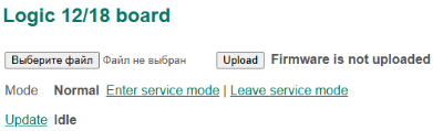
In this section:
- Upload – a button to upload the BMS Logic 12/18 firmware to the SD card. There is the message to the right of the “Upload” button describing the presence of the firmware on the SD card:
- Firmware is not uploaded;
- Firmware is uploaded;
- Mode – a mode in which the BMS stays:
- Normal – the BMS communicates with the BMS Logic 12/18 boards to get measurements and do cells balancing;
- Service – the BMS does not communicate with the BMS Logic 12/18 boards and is ready to update their firmware;
- Enter service mode, Leave service mode – links for switching to the Service or Normal mode;
- Update – a link by clicking on which updating the BMS Logic 12/18 will start (before clicking it’s necessary to upload the firmware to the SD card and switch the BMS to the “Service mode”). The messages describing the updating process shown:
- Starting bootloader;
- Bootloader started;
- Bootloader failed;
- Done – updated successfully;
- Parsing firmware error;
- No connection;
- Start programming session error;
- Erasing error;
- Programming data error;
- Stop programming session error.
To update the BMS Logic 12/18 board follow the steps:
- Upload the firmware to the SD card (the file must be in the format Motorola S-Record, SREC).
- Check that the firmware is uploaded (reselect the menu “External equipment → Display board”).
- Switch the BMS Main 2.x to the “Service mode” (click the “Enter service mode” link).
- Change the address of the BMS Logic 12/18 to 0 (the board will start its bootloader).
- Click the “Update” link.
- Periodically monitor the update process – click on the menu "External equipment → Logic 12/18 board" (update takes about 60 seconds).
Main X board
BMS Main 2.x can connect to BMS Main X strings controller.
To go to the configuration interface, select the menu "External equipment → BMS Main X":
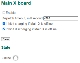
In this section:
- Enable – a flag to enable communication with BMS Main X;
- Dispatch timeout – timeout for received messages;
- Online – connection status.