

3.2 BMS and battery state
Configuration
BMS and battery state
The BMS Main 2.x board continuously evaluates the state of the battery system.
BMS state
System Overview
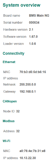
To display information about the board including connection parameters select the menu item “System → Overview”:
In this section:
- Board name (“BMS Main NG”);
- Serial number – serial number of the board assigned by the manufacturer;
- Hardware version – revision of the board;
- Software version – revision of the firmware;
- Loader version – revision of the bootloader;
- Ethernet connection settings;
- CANopen identifier;
- Board address according to the Modbus RTU specification;
- Wi-Fi information.
Signals / Errors
To display the state of input and output signals, error flags select the menu “System → Signals / Errors”:
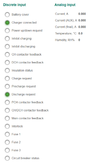
Description of discrete input signals is available in Input signals.
Analog input signals in this section:
- Current – current through the battery, A;
- Current (AUX) – current through series of cells (additional sensor), A;
- Current (mean) – current through the battery (mean value), A;
- Temperature – temperature, measured by the BMS Main 2.x, °C;
- Humidity – humidity, RH%.
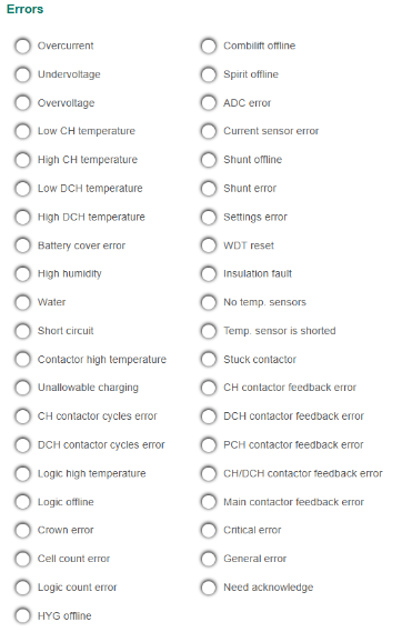
Description of errors is available in Errors.
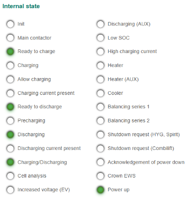
Description of internals states is available in Internal signals.
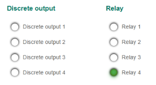
Output signals in this section:
- Physical state of discrete output 1..4;
- Physical state of relay 1..4.
Error journal
To display the content of the errors journal, select the menu “System → Error journal”:
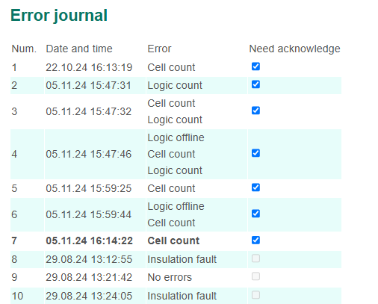
The table contains detected errors.
Header columns:
- Num. – number of a record (from 1 to 32);
- Date and time – date and time of a record;
- Error – error names;
- Need acknowledge – flag showing the need to acknowledge a record.
The errors journal is cyclical: after all 32 positions are filled, a new record will be placed at position “1”. The last entry is marked bold.
When adding a new record to the journal, the flag "Need acknowledge" is set and the corresponding error is generated. To clear the “Need acknowledge” error, you need to clear the “Need acknowledge” flags for all journal entries and click on the “Acknowledge” button.
Energy
To display information about the received and consumed energy, select the menu “System → Energy”:
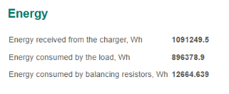
In this section:
- Energy received from the charger (energy of the positive direction), Wh;
- Energy consumed by the load (energy of negative direction), Wh;
- Energy consumed by balancing resistors, Wh.
Battery state
Logic and cell overview
To display the minimum and maximum temperature and voltage of the cells, select the menu “Logic / Cell → Overview”:
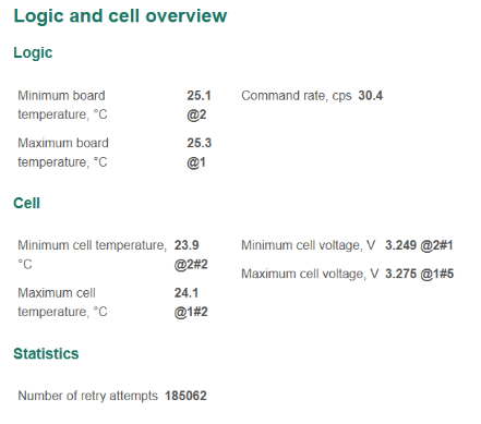
In this section:
- BMS Logic board parameters:
- Minimum board temperature, °C;
- Maximum board temperature, °C;
- Command rate – rate of data exchange with BMS Logic boards, commands per second;
- Cell parameters (after the temperature and voltage values, the symbols "@" indicate the address of the BMS Logic board and the cell.):
- Minimum cell temperature, °C;
- Maximum cell temperature, °C;
- Minimum cell voltage, V;
- Maximum cell voltage, V;
- Statistics:
- Number of retry attempts – counter of retry attempts showing the communication problems with BMS Logic devices.
Logic and cell measurements
To display information about a particular BMS Logic board, select the menu “Logic / Cell → Measurements”:
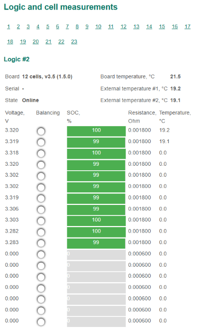
This section provides all information about the selected BMS Logic board:
- Board – maximum number of cells served by the BMS Logic board, hardware and software version of the board;
- Serial – serial number of the board (only for BMS Logic 12 and BMS Logic 18);
- State:
- Not present – board is not present;
- Online – board is present and the connection with it is established;
- Offline – board is present and the connection with it is lost;
- Board temperature, °C;
- External temperature #1 – temperature measured by sensor 1, °C;
- External temperature #2 – temperature measured by sensor 2, °C;
- Cell parameters:
- Voltage – cell voltage, V;
- Balancing – cell balancing indicator;
- SOC – state of charge, %;
- Resistance – cell resistance, Ohm;
- Temperature – cell temperature, °C.
Cell summary
To display summary information about all battery cells, select the menu “Logic / Cell → Cell summary”:
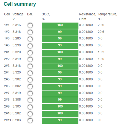
This section contains a summary table with parameters of all cells:
- Cell – BMS Logic address and the position of the cell for which the data is given;
- Voltage – cell voltage, V;
- Bal. – cell balancing indicator;
- SOC – state of charge, %;
- Resistance – cell resistance, Ohm;
- Temperature – cell temperature, °C.