3. Configuration
Last modified by Admin on 2026/02/20 20:42
Configuration
Connecting device to PC
To connect the BMS Logic 18S to a PC, use the BMS USB-RS485 adapter. It allows to power and communicate with the BMS Logic 18S:
- Connect the BMS USB-RS485 to the BMS Logic 18S:
a) the communication circuits (X3 -> X3);
b) the circuits of cells (X5 -> X1). - Connect the BMS USB-RS485 to a PC using a mini-USB or USB-C cable.
- Turn all the BMS USB-RS485’s switches to the “I” position.
The assembly drawings of the harnesses between the BMS USB-RS485 and BMS Logic 18S are given below.
Communication and power cable
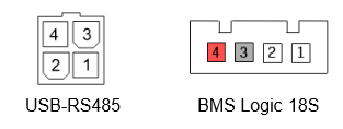 The wires of the communication and power cable must be connected according to the following table:
| Circuit name | Pin of the connector to BMS USB-RS485 | Pin of the connector to BMS Logic 18S |
| RS485_A | 1 | 2 |
| RS485_B | 2 | 1 |
| +5V | 3 | 4 |
| GND | 4 | 3 |
Cells cable
 The wires of the cells cable must be connected according to the following table:
| Circuit name | Pin of the connector to BMS USB-RS485 | Pin of the connector to BMS Logic 18S |
| V- | 1 | 9 |
| C1 | 13 | 1 |
| C2 | 2 | 10 |
| C3 | 14 | 2 |
| C4 | 3 | 11 |
| C5 | 15 | 12 |
| C6 | 4 | 3 |
| C7 | 5 | 13 |
| C8 | 6 | 4 |
| C9 | 7 | 14 |
| C10 | 8 | 15 |
| C11 | 9 | 16 |
| C12 | 10 | 17 |
| C13 | 19 | 18 |
| C14 | 8 | 19 |
| C15 | 20 | 5 |
| C16 | 9 | 20 |
| C17 | 21 | 6 |
| C18 | 10 | 21 |
Setting the device address
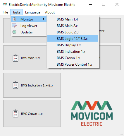
Launch the ElectricDeviceMonitor, then select the “BMS Logic 12/18 3.x” monitor:
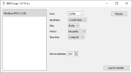
Set the following settings to connect to the BMS Logic 18S:
- 115200 bps,
- 8 bits,
- no parity,
- 1 stop bit,
- device address 247.
The address 247 is a service address that the device will always answer.
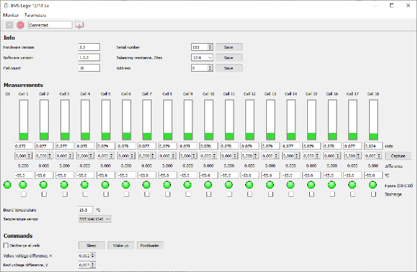
Check the connection with the BMS Logic 18S is established.
Set the needed device address and click the “Save” button: