2. Installation and connection
Installation and connection
Safety rules
Before use, configure the system. Proper operation of the BMS is possible only if it is correctly configured.
It is not recommended to use the system in batteries formed by several series of cells connected in parallel. To increase capacity, it is recommended to connect several cells in parallel groups, and then connect the groups in series.
Installation procedure
The mounting area of the BMS Logic 12S must be protected from mechanical particles (dust, dirt, large objects) and water. The BMS Logic 12S is recommended to be placed close to the cells it controls, but away from high current circuits to reduce interference to measuring circuits and increase overall reliability of installation.
The installation site must provide convenient access for subsequent connection to the device’s headers.
The BMS Logic 12S has a heat sink to dissipate the heat generated during the balancing of the cells. When used in enclosed enclosures, heat must be dissipated from the sink, otherwise it may damage the device.
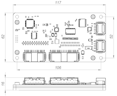
Overall and mounting dimensions of the BMS Logic 12S are shown below.
| Parameter | Value |
| Overall dimensions (length × width × height), mm | 117 × 62 × 16 |
| Mounting dimensions (length × width), mm | 106 × 52 |
| Mounting holes | M4 |
Headers
The BMS Logic 12S is designed to measure temperature and voltage of 12 battery cells.
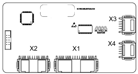
X1 – header for cells and temperature sensors
Receptacle Housing: Hirose ZE05-24DS-HU/R. Terminals: Hirose ZE05-2022SCF

| Pin | Name | Description |
| 1 | C1 | Cell #1 (minimum potential with respect to V-) |
| 2 | C3 | Cell #3 |
| 3 | C6 | Cell #6 |
| 4 | C8 | Cell #8 |
| 5 | TEMPG1 | Ground of the thermistor #1 |
| 6 | TEMPG2 | Ground of the thermistor #2 |
| 7 | TEMPG4 | Ground of the thermistor #4 |
| 8 | TEMPG5 | Ground of the thermistor #5 |
| 9 | V- | Minus of the cell stack |
| 10 | C2 | Cell #2 |
| 11 | C4 | Cell #4 |
| 12 | C5 | Cell #5 |
| 13 | C7 | Cell #7 |
| 14 | C9 | Cell #9 |
| 15 | C10 | Cell #10 |
| 16 | C11 | Cell #11 |
| 17 | C12 | Cell #12 (maximum potential of the cell stack) |
| 18 | - | - |
| 19 | TEMP1 | Signal from the thermistor #1 |
| 20 | TEMP2 | Signal from the thermistor #2 |
| 21 | TEMP3 | Signal from the thermistor #3 |
| 22 | TEMPG3 | Ground of the thermistor #3 |
| 23 | TEMP4 | Signal from the thermistor #4 |
| 24 | TEMP5 | Signal from the thermistor #5 |
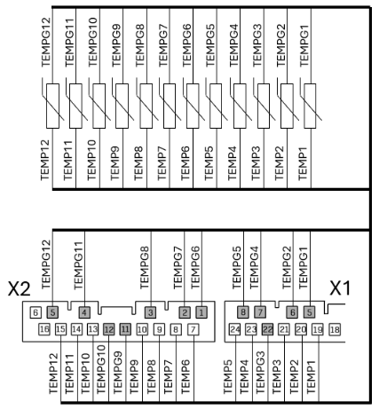
X2 – header for temperature sensors
Receptacle Housing: Hirose ZE05-16DS-HU/R. Terminals: Hirose ZE05-2022SCF
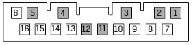
| Pin | Name | Description |
| 1 | TEMPG6 | Ground of the thermistor #6 |
| 2 | TEMPG7 | Ground of the thermistor #7 |
| 3 | TEMPG8 | Ground of the thermistor #8 |
| 4 | TEMPG11 | Ground of the thermistor #11 |
| 5 | TEMPG12 | Ground of the thermistor #12 |
| 6 | - | - |
| 7 | TEMP6 | Signal from the thermistor #6 |
| 8 | TEMP7 | Signal from the thermistor #7 |
| 9 | TEMP8 | Signal from the thermistor #8 |
| 10 | TEMP9 | Signal from the thermistor #9 |
| 11 | TEMPG9 | Ground of the thermistor #9 |
| 12 | TEMPG10 | Ground of the thermistor #10 |
| 13 | TEMP10 | Signal from the thermistor #10 |
| 14 | TEMP11 | Signal from the thermistor #11 |
| 15 | TEMP12 | Signal from the thermistor #12 |
| 16 | - | - |
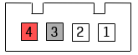
X3, X4 – headers for communication with BMS Main
Receptacle Housing: Hirose ZE05-4S-HU/R. Terminals: Hirose ZE05-2022SCF
| Pin | Name | Description |
| 1 | RS485_B | RS-485 line B for communication with the BMS Main |
| 2 | RS485_A | RS-485 line A for communication with the BMS Main |
| 3 | GND | Ground |
| 4 | +5V | Supply voltage 5V |
Indicators
DS13 – mode indicator
| State | Description |
| Blinking | Connection between the BMS Main and the device is established |
| Short flashing (~50 milliseconds in a second) | The device is measuring voltage and temperature. No communication between the BMS Main and the device |
| Long flashing (1 second in a 2 second period) | The device is in the bootloader mode |
Connection procedure
Connection to BMS Main
To connect the BMS Main to BMS Logic 12S do the following steps:
- Connect the BMS Main to the first BMS Logic 12S (P15 -> X3).
- Connect the BMS Logic 12S to each other (X4 -> X3).
- Connect a 120 Ohm termination resistor directly to the X4 connector of the last BMS Logic 12S.
Connecting battery cells
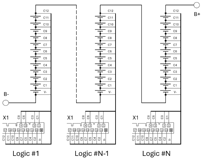
To connect the battery cells, follow figure below. Incorrect connection of the cells can damage the BMS Logic 12S.
Begin the connection with the negative of the battery: the "V-" of the first BMS Logic 12S is connected to "B-", then the first cell (C1) of the battery is connected, then the second (C2), etc. The “V-“ of the next BMS Logic 12S is connected to the C12 of the previous BMS Logic 12S. If not all inputs of the cells are used, then the remaining inputs are connected to the cell with the highest potential.
Connecting thermistors
Thermistors should be fastened to the cells, excluding short circuits to the cell terminals (for example, isolate thermistors with heat shrink). For reliable operation, it is recommended to use all thermistors (a temperature sensor per cell).