

2. Connection
Last modified by Admin on 2025/03/18 12:58
Connection
Safety rules
Device connectors
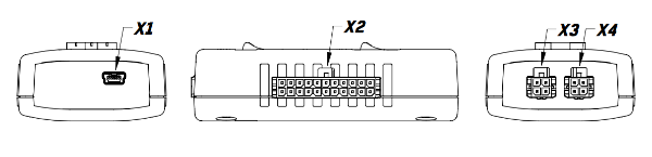
The location and designation of the connectors are shown on figure below.
Headers
Х1 – mini-USB connector for communication with PC.
X2 – battery cells emulator connector
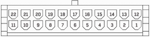
| Pin | Name | Description |
| 1 | V- | Minus of the cell stack |
| 2 | C2 | Cell 2 |
| 3 | C4 | Cell 4 |
| 4 | C6 | Cell 6 |
| 5 | C8 | Cell 8 |
| 6 | C10 | Cell 10 |
| 7 | C12 | Cell 12 |
| 8 | C14 | Cell 14 |
| 9 | C16 | Cell 16 |
| 10 | C18 | Cell 18 |
| 11 | NC | - |
| 12 | NC | - |
| 13 | C1 | Cell 1 (minimum potential with respect to V-) |
| 14 | C3 | Cell 3 |
| 15 | C5 | Cell 5 |
| 16 | C7 | Cell 7 |
| 17 | C9 | Cell 9 |
| 18 | C11 | Cell 11 |
| 19 | C13 | Cell 13 |
| 20 | C15 | Cell 15 |
| 21 | C17 | Cell 17 |
| 22 | - | - |
Х3, X4 – RS-485 interface connectors for communication with BMS Logic

| Pin | Name | Description |
| 1 | RS485_A | A line of the external RS-485 bus |
| 2 | RS485_B | B line of the external RS-485 bus |
| 3 | 5V | Galvanically isolated external voltage for BMS Logic supply |
| 4 | GND | Galvanically isolated ground |