
Settings
Control
General parameters
General parameters of BMS Main X are configured in the «Control → General» section:

In this section:
- Initialization delay – a delay before processing functions after finishing device initialization (initialization includes current sensors calibration and battery modules search), millisecond.
Battery modules
The BMS Main X allows up to 32 battery modules to be connected in parallel.
Flags for enabling battery modules are configured in the "Control → Modules → Enable (modules 1 to 8)" and "Control → Modules → Enable (modules 9 to 32)" section:

The network addresses of the battery modules are configured in the "Control - Modules - Node IDs" section:

Each module in a battery must have a unique address. You can change the address in the battery module settings in the “Connectivity → CAN” section of the BMS Main or BMS Mini S / BMS Mini 2 settings.
In corresponding section you can set up minimum number of found modules to finish initialization.
Calculation of battery parameters
The BMS Main X device calculates battery parameters based on user settings.
Calculation of the battery state of charge (SOC) is configured in the "Control - Calculation - Final SOC" section:

The following battery SOC calculation methods are supported:
- Minimal SOC – SOC of the modular battery is assumed to be the minimum SOC among the battery modules;
- Average SOC – SOC of the modular battery is taken equal to the arithmetic average of the SOC of the battery modules;
- Min-Max SOC – the battery SOC is calculated based on the minimum and maximum SOC of the modules. Final SOC will be a) 100% if any module has 100% SOC, b) 0% if any module has 0% SOC;
- Max-Min SOC – the battery SOC is calculated based on the minimum and maximum SOC of the modules. Final SOC will be a) 100% if all modules have 100% SOC, b) 0% if all modules have 0% SOC;
Calculation of the battery state of health (SOH) is configured in the "Control → Calculation → Final SOH" section. The following battery SOH calculation methods are supported:
- Minimal SOH – SOH of the modular battery is assumed to be the minimum SOH among the battery modules;
- Average SOH – SOH of the modular battery is taken equal to the arithmetic average of the SOH of the battery modules.
Main contactor
The BMS Main X device controls the main contactor. The main contactor is usually placed in the common (minus) battery line for opening the charge and discharge circuits in case of sealing of the charging or discharging contactors.
The Main contactor algorithm supports the following modes:
- Always on;
- Automatic, when the main contactor closes by the internal charging and discharging algorithms at the same time with Precharging, Charging, Discharging and Charging/Discharging contactors.
In “Always on” mode main contactor closes if all the following is true:
- Other contactors are open;
- There are no errors from the "Errors 1, 2 ..." bitfileds.
In “Always on” mode main contactor opens if all the following is true:
- Other contactors are open;
- There is an error from the the "Errors 1, 2 ..." bitfileds.
In “Automatic” mode, the main contactor closes by internal algorithms at the same time with other contactors.
To change the parameters of the main contactor, select the "Control → Main contactor" section:

In this section:
- Enable – a flag to enable the main contactor control;
- Algorithm – main contactor control algorithm:
- Always on – contactor is always closed;
- Automatic – contactor closes by internal charge and discharge algorithms;
- Time to keep the contactor closed before closing the others – a time for other contactors to be open after the main contactor is closed, millisecond;
- Delay before opening the contactor – a time which is used to detect conditions for opening the contactor, millisecond;
- Keep the contactor open until the device is restarted – a flag for keeping the main contactor open until the system is reset;
- Errors to open the main contactor – error flags that cause the contactor to open.
Charging status
To change the parameters for generating status signals when charging the battery, select the section “Control → Charging status”:

In this section:
- Current corresponding to charging – a current level to set the "Charging current present" signal, A;
- Current corresponding to no charging – a current level to clear the "Charging current present" signal, A.
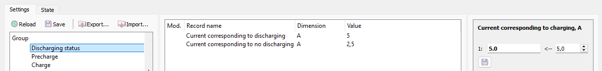
Discharging status
To change the parameters for generating status signals when discharging the battery, select the section “Control → Discharging status”:
Charge
The BMS Main X device manages the parallel connection of the battery modules and the connection of the battery to the charging circuit.
The device supports the following charging modes:
- Charging is always allowed (Always on) – the device ignores voltage and current unbalance of the battery modules and commands to close the charging contactors of the battery modules and the main charging contactor.
- Charging is allowed provided that all battery modules are balanced (Balanced).
- Charging is allowed for most balanced battery modules (Partially balanced). Unbalanced modules are disconnected from the common bus and do not participate in the charging.
The device controls two processes: joining battery modules and closing the main charging contactor.
The operation of the joining battery modules is described by the following steps:
- Battery modules are disabled. When the “Join to charge” request is received and the voltage and current unbalance errors (Voltage unbalance (CH), Current unbalance (CH), Charging current unbalance) are cleared, go to step 2.
- Checking the voltage unbalance of battery modules (the duration of the check is set in the settings). If there is no imbalance or errors are ignored (“Always on” and “Partially balanced”), go to step 3, otherwise open all charging contactors, and go to step 1.
- Closing the precharging contactors of the battery modules (optional). Go to step 4.
- Closing the charging contactors of the battery modules. The battery modules are self-balancing. Go to step 5.
- Checking intermodular balancing currents (the duration of the check is set in the settings). If there is no current unbalance (“Current unbalance (CH)”) or errors are ignored (“Always on”), go to step 6, otherwise open all charging contactors, and go to step 1.
- The battery modules are joined. If the “Join to charge” request is cleared or the "Charging current unbalance" and "Critical error" errors occur, go to step 1.
The operation of the main charging contactor is described in the following steps:
- The main charging contactor is open. When the “Charge request” is received, the voltage and current unbalance errors (“Voltage unbalance (CH)”, “Current unbalance (CH)”, “Charging current unbalance”) are cleared, and the battery modules are joined, go to step 2.
- Closing the main precharging contactor (optional). Go to step 3.
- Closing the main charging contactor ("Charging" signal). Go to step 4.
- The main charging contactor is closed. If the "Charge request" is cleared, the battery modules are disconnected, or the "Critical error" occurs, go to step 1.
The command to turn on the main charging contactor (“Charging”) can be issued both to the upper-level system via the CAN bus (external), and on the opto-relay of the device that serves to directly control the main charging contactor.
In addition to controlling the charging contactors, the charge controller calculates and transmits to the upper-level system the value of the maximum allowable current, which can be used to charge the modular battery (“Charge current limit”). The calculation of the charging current of the entire battery is performed based on the number of battery modules operating per charge and the values of the current limits transmitted by them.
The battery charge management is configured in the "Control - Charge" section:

In this section:
- Enable – a flag to enable battery charge controller;
- Algorithm:
- Always on – charging is always allowed;
- Balanced – charging is allowed provided that all battery modules are balanced;
- Partially balanced – charging is allowed for most balanced battery modules;
- Current corresponding to charging – a current level to set the "Charging current present" signal, A;
- Current corresponding to no charging – a current level to clear the "Charging current present" signal, A;
- Maximum current to rejoin modules – a maximum allowable current at which rejoining of battery modules is allowed, A;
- Checking voltages time – a time of checking voltages of battery modules, ms;
- Pre-balancing modules time – a time of pre-charging battery modules, ms;
- Balancing modules time – a time of balancing battery modules, ms;
- Control the precharging relay – a flag to control the main precharging contactor;
- Precharging time – a time of precharging, ms;
- Cancel charging without a delay;
- Canceling charging time – a delay before opening the main charging contactor, ms;
- Limit charging current – a flag that allows to limit the charging current of a modular battery so that the current of each battery module does not exceed its maximum allowable charge current;
- Slew rate – a rate of change of the charge current limit when the “Limit charging current” flag is set, А/s;
- Disconnect modules not ready to charge – a flag for disconnecting modules that have the “Ready to charge” signal cleared.
Discharge
The BMS Main X device manages the parallel connection of the battery modules and the connection of the battery to the discharging circuit
The device supports the following discharging modes:
- Discharging is always allowed (Always on) – the device ignores voltage and current unbalance of the battery modules and commands to close the discharging contactors of the battery modules and the main discharging contactor.
- Discharging is allowed provided that all battery modules are balanced (Balanced).
- Discharging is allowed for most balanced battery modules (Partially balanced). Unbalanced modules are disconnected from the common bus and do not participate in the discharging.
The device controls two processes: joining battery modules and closing the main discharging contactor.
The operation of the joining battery modules is described by the following steps:
- Battery modules are disabled. When the “Join to discharge” request is received and the voltage and current unbalance errors (Voltage unbalance (DCH), Current unbalance (DCH), Discharging current unbalance) are cleared, go to step 2.
- Checking the voltage unbalance of battery modules (the duration of the check is set in the settings). If there is no imbalance or errors are ignored (“Always on” and “Partially balanced”), go to step 3, otherwise open all discharging contactors, and go to step 1.
- Closing the precharging contactors of the battery modules (optional). Go to step 4.
- Closing the discharging contactors of the battery modules. The battery modules are self-balancing. Go to step 5.
- Checking intermodular balancing currents (the duration of the check is set in the settings). If there is no current unbalance (“Current unbalance (DCH)”) or errors are ignored (“Always on”), go to step 6, otherwise open all discharging contactors, and go to step 1.
- The battery modules are joined. If the “Join to discharge” request is cleared or "Discharging current unbalance" and "Critical error" errors occur, go to step 1.
The operation of the main discharging contactor is described in the following steps:
- The main discharging contactor is open. When the “Discharge request” is received, the voltage and current unbalance errors (“Voltage unbalance (DCH)”, “Current unbalance (DCH)”, “Discharging current unbalance”) are cleared, and the battery modules are joined, go to step 2.
- Closing the main precharging contactor (optional). Go to step 3.
- Closing the main discharging contactor ("Discharging" signal). Go to step 4.
- The main discharging contactor is closed. If the "Discharge request" is cleared, the battery modules are disconnected, or the "Critical error" occurs, go to step 1.
The command to turn on the main discharging contactor (“Discharging”) can be issued both to the upper-level system via the CAN bus (external), and on the opto-relay of the device that serves to directly control the main discharging contactor.
In addition to controlling the discharging contactors, the discharge controller calculates and transmits to the upper-level system the value of the maximum allowable current, which can be used to discharge the modular battery (“Discharge current limit”). The calculation of the discharging current of the entire battery is performed based on the number of battery modules operating per discharge and the values of the current limits transmitted by them.
The battery discharge management is configured in the "Control - Discharge" section:

In this section:
- Enable – a flag to enable battery discharge controller;
- Algorithm:
- Always on – discharging is always allowed;
- Balanced – discharging is allowed provided that all battery modules are balanced;
- Partially balanced – discharging is allowed for most balanced battery modules;
- Current corresponding to discharging – a current level to set the "Discharging current present" signal, A;
- Current corresponding to no discharging – a current level to clear the "Discharging current present" signal, A;
- Maximum current to rejoin modules – a maximum allowable current at which rejoining of battery modules is allowed, A;
- Checking voltages time – a time of checking voltages of battery modules, ms;
- Pre-balancing modules time – a time of precharging battery modules, ms;
- Balancing modules time – a time of balancing battery modules, ms;
- Control the precharging relay – a flag to control the main precharging contactor;
- Precharging time – a time of precharging, ms;
- Cancel discharging without a delay;
- Canceling discharging time – a delay before opening the main discharging contactor, ms;
- Limit module current – a flag that allows to limit the discharging current of a modular battery so that the current of each battery module does not exceed its maximum allowable discharge current;
- Slew rate – a rate of change of the discharge current limit when the “Limit module current” flag is set, А/s;
- Disconnect modules not ready to discharge – a flag for disconnecting modules that have the “Ready to discharge” signal cleared.
Charge/Discharge
The BMS Main X can control the charging/discharging contactor that is used to both charge and discharge the battery.
The charge/discharge contactor (“Charging/Discharging” signal) receives a “Charging” signal (generated by the charge controller) if a “Charge request” signal is received from the upper-level system. In all other cases, the "Discharging" signal is output to the contactor (generated by the discharge controller).
The charge/discharge contactor control is configured in the “Control – Charge/Discharge” section:

In this section:
- Enable – a flag to enable the charge/discharge controller.
Module balancing
The BMS Main X device supports active balancing of battery modules both in the process of charging and in the process of discharging the battery.
When the battery is charging, balancing is performed by disconnecting the most charged battery modules from the common bus. Before disconnecting the modules, the BMS Main X sends a request to the upper-level system (charger) to reduce the charge current to zero, and after the current becomes zero, disconnects the most charged battery modules.
When the battery is discharging, balancing is performed by disconnecting the most discharged battery modules from the common bus. Battery modules are disconnected only if the battery discharge current has dropped to the threshold value set in the device settings.
Module balancing is configured in the “Control – Module balancing” section:

In this section:
- Balance on charging – a flag to enable module balancing when the battery is charging;
- Delta voltage – a voltage difference at which the most charged modules are switched off (those modules whose voltage exceeds the minimum voltage among the modules by the “Delta voltage” value are switched off), V;
- Delta current – a current difference at which the most charged modules are switched off (those modules are switched off, the charge current of which is less than the maximum charge current among the modules by the “Delta current” value), A;
- Waiting time – a time the battery modules are in the disconnected state (after this time, the modules previously disconnected during the balancing process are reconnected to the common bus), s;
- Balance on discharging – a flag to enable module balancing when the battery is discharging;
- Required discharging current – a value of the discharge current at which the device switches off the most discharged battery modules, A.