
2. Установка и подключение
Installation and connection
Установка
Место крепления устройства должно быть защищено от попадания механических объектов (пыли, грязи, крупных объектов) и воды.
Место крепления должно предполагать удобный доступ к устройству для подключения других элементов батарейной системы: батарейных модулей, термисторов, контакторов.
Габаритные и установочные размеры BMS Main X приведены ниже.


| Параметр | Значение |
| Габаритные размеры (длина × ширина × высота), мм | 105 × 115 × 15 |
| Установочные размеры (длина × ширина), мм | 99 × 109 |
| Установочные отверстия | M3 |
Подключение
Разъёмы
Расположение и обозначение разъемов показаны на рисунке ниже.

Х1 – разъём питания
Ответный разъем: Molex 436450200. Terminals: Molex 43030

| Pin | Name | Description |
| 1 | V+ | Supply voltage 18÷36V |
| 2 | GND | Ground |
X2 – header for USB
X3 – header for CAN (INT) interface
Ответный разъем: Molex 430250400. Terminals: Molex 43030

| Pin | Name | Description |
| 1 | СAN_INT_H | CAN-H line of the internal CAN bus (communication with battery modules) |
| 2 | CAN_INT_L | CAN-L line of the internal CAN bus (communication with battery modules) |
| 3 | CAN_INT_5V | Isolated 5V power supply for internal devices, max 200 mA |
| 4 | CAN_INT_GND | Isolated ground |
Х4 – header for RS-485 interface
Ответный разъем: Molex 430250400. Terminals: Molex 43030
| Pin | Name | Description |
| 1 | RS485_A | A line of the external RS-485 bus |
| 2 | RS485_B | B line of the external RS-485 bus |
| 3 | - | - |
| 4 | RS485_GND | Isolated ground |
J1 – jumper for switching RS-485 terminal resistor
To connect the terminal resistor between the RS485_A and RS485_B lines, install the jumper J1 according to the following figure:
Х5 – header for CAN (EXT) interface
Ответный разъем: Molex 430250400. Terminals: Molex 43030
| Pin | Name | Description |
| 1 | СAN_EXT_H | CAN-H line of the external CAN bus (communication with a top-level system) |
| 2 | CAN_EXT_L | CAN-L line of the external CAN bus (communication with a top-level system) |
| 3 | CAN_EXT_5V | Isolated 5V power supply for external devices, max 200 mA |
| 4 | CAN_EXT_GND | Isolated ground |
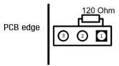
J2 – jumper for switching CAN (EXT) terminal resistor
To connect the terminal resistor between the CAN_EXT_H and CAN_EXT_L lines, install the jumper J2 according to the following figure:
Х6 – header for sold-state relays
Ответный разъем: Molex 430250600. Terminals: Molex 43030

| Pin | Name | Description |
| 1 | NO1 | Normally open contact of the relay 1 |
| 2 | NO2 | Normally open contact of the relay 2 |
| 3 | NO3 | Normally open contact of the relay 3 |
| 4 | COM1 | Common contact of the relay 1 (55V, 2A) |
| 5 | COM2 | Common contact of the relay 2 (55V, 2A) |
| 6 | COM3 | Common contact of the relay 3 (55V, 2A) |
X7 – header for discrete inputs/outputs
Ответный разъем: Molex 430251800. Terminals: Molex 43030

| Pin | Name | Description |
| 1 | GND | Discrete input 1 “dry contact” (ground) |
| 2 | GND | Discrete input 2 “dry contact” (ground) |
| 3 | GND | Discrete input 3 “dry contact” (ground) |
| 4 | GND | Discrete input 4 “dry contact” (ground) |
| 5 | - | - |
| 6 | GND | Discrete output 1 (ground) |
| 7 | GND | Discrete output 2 (ground) |
| 8 | GND | Discrete output 3 (ground) |
| 9 | GND | Discrete output 4 (ground) |
| 10 | D_IN1 | Discrete input 1 “dry contact” (+5V) |
| 11 | D_IN2 | Discrete input 2 “dry contact” (+5V) |
| 12 | D_IN3 | Discrete input 3 “dry contact” (+5V) |
| 13 | D_IN4 | Discrete input 4 “dry contact” (+5V) |
| 14 | - | - |
| 15 | D_OUT1 | Discrete output 1 (+5V, 20mA) |
| 16 | D_OUT2 | Discrete output 2 (+5V, 20mA) |
| 17 | D_OUT3 | Discrete output 3 (+5V, 20mA) |
| 18 | D_OUT4 | Discrete output 4 (+5V, 20mA) |
Х8 – header for temperature sensors
Ответный разъем: Molex 430250400. Terminals: Molex 43030
| Pin | Name | Description |
| 1 | TEMPG1 | Ground of the thermistor 1 |
| 2 | TEMPG2 | Ground of the thermistor 2 |
| 3 | TEMP1 | Signal from the thermistor 1 |
| 4 | TEMP2 | Signal from the thermistor 2 |