

4.1 Signals
Last modified by Admin on 2026/09/04 11:48
Monitoring
Signals
States of the device's discrete inputs are available in the "Signals → Input discrete signal" section:
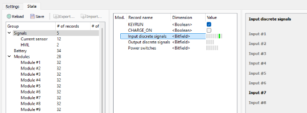
In this section:
- Input #1 - Input #8 – states of the inputs 1-8 respectively.
The states of the discrete output signals are available in the "Signals → Output discrete signals" section:
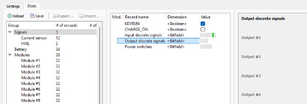
In this section:
- Output #1 - Output #4 – states of the outputs 1-4 respectively.
The states of the power switches are available in the "Signals → Power switches" section:
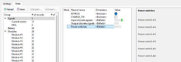
In this section:
- Power switch #1 - Power switch #6 – states of the power switches 1-6 respectively.
Current sensor
The states of the current sensors are available in the "Signals → Current sensor" section:
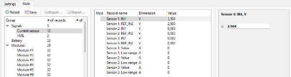
In this section:
- Sensor 1, 2, 3: IN1 – output signal from the current sensor, V;
- Sensor 1, 2, 3: REF_IN2 – signal in the reference line, V;
- Sensor 1, 2, 3: Value – calculated value of the current, A;
- Sensor 1, 2, 3: Low range – calculated value of the lower range current, A.
HVIL
The state of the HVIL is available in the "Signals → HVIL" section:

In this section:
- Current (power off) – high voltage interlock loop current at power off, A;
- Current (power on) – high voltage interlock loop current at power on, A.