

3.2 Inputs and outputs
Configuration
Inputs and outputs
Discrete inputs
The BMS Main 2R device has 4 discrete inputs that detect signal line closing to the virtual ground.
The BMS Main 3 device has 6 discrete inputs that detect signal line closing to the virtual ground, and 2 inputs that detect 9-32V input voltage.
For each discrete input, its assignment and inversion flag are set.
Also, BMS Main 3 has two additional configurable inputs named “KEYRUN” and “CHARGE_ON”, each serves 9-32V input voltage. Those inputs serve as power buttons with additional functions that can be set.
Assignments of discrete inputs are configured in the "Signals → Input discrete signals → Assignments" section:
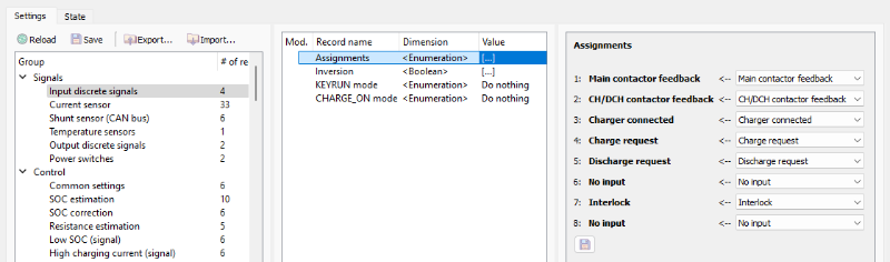
Inversion flags for discrete inputs are configured in the "Signals → Input discrete signals → Inversion" section:

The behavior of “KEYRUN” signal can be configured in the "Signals → Input discrete signals → KEYRUN mode" section:

The behavior of “CHARGE_ON” signal can be configured in the "Signals → Input discrete signals → CHARGE_ON mode" section:

In both “KEYRUN mode” and “CHARGE_ON mode“ sections:
- Do nothing – power on device and do nothing;
- Set “Discharge request” – power on device and set “Discharge request” signal immediately;
- Set “Charge request” – power on device and set “Charge request” signal immediately.
Current sensor
The BMS Main 2R device has an ability to measure battery current by 2 external Hall-Effect current sensors.
The BMS Main 3 device has an ability to measure battery current by 3 external Hall-Effect current sensors.
Current sensor settings are configured in the "Signals → Current sensor" section:
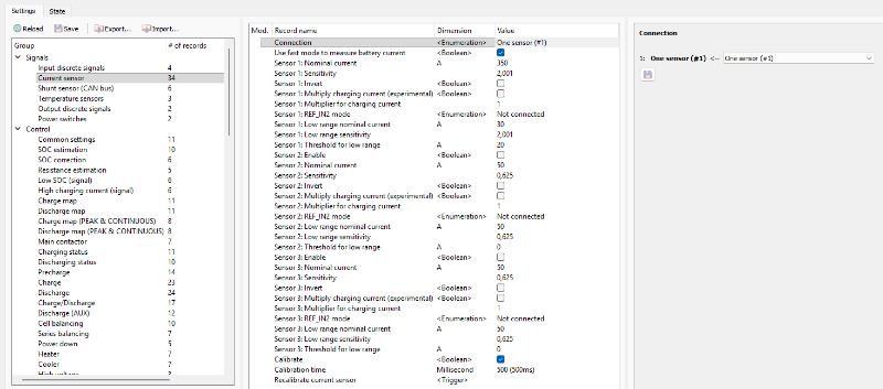
In this section:
- Connection – type of multiple sensors connection
- One sensor (#1) – only first sensor is used to measure the battery current;
- Two sensors (#1 and #2) in parallel – sensors are connected in parallel (the total battery current equals the sum of two sensors);
- Two sensors (#1 and #2) in different branches – sensors located in two halves of the battery (used in batteries with a middle point);
- Use fast mode to measure battery current – a flag to enable faster current measurement;
- Sensor 2, 3: Enable – a flag to enable the second of third current sensor;
- Sensor 1, 2, 3: Nominal current – rated current Inom of the sensor according to the datasheet, А;
- Sensor 1, 2, 3: Sensitivity – sensitivity of the current sensor according to the datasheet, V / Inom.;
- Sensor 1, 2, 3: Invert – invert the sign of the measured value;
- Sensor 1, 2, 3: Multiply charging current (experimental) – an experimental flag for scaling the charging current by given multiplier;
- Sensor 1, 2, 3: Multiplier for charging current – charging current multiplier;
- Sensor 1, 2, 3: REF_IN2 mode – mode of additional analog line:
- Not connected;
- Reference line – reference output of the sensor;
- Low range (for the dual range sensor) - a second output of a dual-range sensor (for example, LEM DHAB series);
- Sensor 1, 2, 3: Low range nominal current - rated current Inom of the low current line of dual range sensor according to the datasheet, А;
- Sensor 1, 2, 3: Low range sensitivity – sensitivity of the low current line of dual range sensor according to the datasheet, V / Inominal.;
- Sensor 1, 2, 3: Threshold for low range – a threshold current value at which the device uses the readings of the high current sensor instead of low current, A;
- Calibrate – a flag to calibrate (find a 0A point) the current sensor when the device is started;
- Calibration time – calibration time of the current sensor, millisecond;
- Recalibrate current sensor – a command to calibrate the current sensor manually.
Shunt sensor (CAN bus)
The BMS Main 3 / BMS Main 2R device has an ability to measure battery current via a shunt sensor, connected to the CAN bus.
Shunt sensor settings are configured in the "Signals → Shunt sensor (CAN bus)" section:

In this section:
- Enable – a flag to start interaction with the BMS Current Sensor (if interaction is enabled, then BMS doesn’t use Hall-Effect current sensor which settings are described in the section "Signals → Current sensor");
- Node ID – an address of BMS Current Sensor in the CANopen network;
- Invert – a flag to invert current measurements;
- Receive timeout – a timeout for receiving messages from the BMS Current Sensor (if no data is being received from the current sensor during this time, the “Shunt offline” flag is set), millisecond;
- Mean value threshold – TM level, A (if module of instantaneous current (II) which is received from the shunt sensor is between TM and T0, the BMS will use mean value of current IM; if II is greater than TM, the BMS will use instantaneous value of current II);
- Zero threshold – T0 level, A (if module of instantaneous current (II) which is received from the shunt sensor is lower than T0, the BMS will assume that current flowing through the battery is zero).
Temperature sensors
Temperature sensors settings are configured in the "Signals → Temperature sensors" section:

In this section:
- Type of cell temperature sensors – a type of temperature sensors connected to BMS Logic devices and used to measure cells temperature;
- Unused cell temperature sensors – a bitfield to select unused temperature sensors on each BMS Logic;
- Type of temperature sensors 1 and 2 – a type of temperature sensors connected to BMS Main 3 / BMS Main 2R.

External 1-2 signals
External signals are the signals that can be generated depending on other internal signals.
To change the conditions of External 1-2 signals generation, open the "Signals → External 1-2 signals" section:

In this section:
- Internal signals to generate the 'External 1' signal – a bitfield to choose the internal signals which will generate External 1 signal;
- Internal signals to generate the 'External 2' signal – a bitfield to choose the internal signals which will generate External 2 signal.
Output discrete signals
The BMS Main 2R and BMS Main 3 devices have 4 open drain type outputs.
For each discrete output, its assignment and inversion flag are set.
Assignments of discrete outputs are configured in the "Signals → Output discrete signals → Assignments" section:

Inversion flags for discrete outputs are configured in the "Signals → Output discrete signals → Inversion" section:
Power switches
The BMS Main 2R device has 4 power relays to drive contactors.
The BMS Main 3 device has 6 power switches to drive contactors.
For each switch, its assignment and inversion flag are set.
Assignments of power switches and relays are configured in the "Signals → Power switches → Assignments" section:
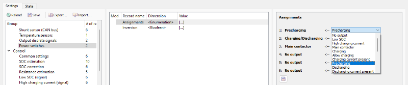
Inversion flags for switches are configured in the “Signals → Power switches → Inversion” section:
