
Installation and connection
Safety rules
To perform the protection functions, the BMS must be able to disconnect the battery from the load and charger. To do this, at least one contactor able to break the load and charge circuits must be connected to the BMS.
Before use, configure the system. Proper operation of the BMS is possible only if it is correctly configured.
Installation procedure
The mounting location of the BMS Main 2R device must be protected from mechanical particles (dust, dirt, large objects) and water. The installation location must provide easy access for subsequent connection to the device connectors.
Overall and mounting dimensions are shown in figure below.

| Parameter | Value |
| Overall dimensions (length × width × height), mm | 120 × 120 × 16 |
| Mounting dimensions (length × width), mm | 114 × 114 |
| Mounting holes | M3 |
Headers
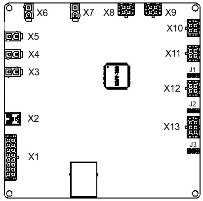
The location and designation of connectors on the BMS Main 2R device are shown below.
X1 – header for discrete inputs and outputs
Receptacle Housing: Hirose ZE05-8DS-HU/R. Terminals: Hirose ZE05-2022SCF

| Pin | Name | Description |
| 1–8 | GND | Ground |
| 9 | DO_1 | Discrete output 1 (+5V, 20mA) |
| 10 | DO_2 | Discrete output 2 (+5V, 20mA) |
| 11 | DO_3 | Discrete output 3 (+5V, 20mA) |
| 12 | DO_4 | Discrete output 4 (+5V, 20mA) |
| 13 | DI_4 | Discrete input 4 (“dry contact”, +5V) |
| 14 | DI_3 | Discrete input 3 (“dry contact”, +5V) |
| 15 | DI_2 | Discrete input 2 (“dry contact”, +5V) |
| 16 | DI_1 | Discrete input 1 (“dry contact”, +5V) |
X2 – miniUSB connector
The miniUSB connector is used to configure the parameters of the BMS Main 2R device.
X3 – header for power supply
Receptacle Housing: Molex 39012020. Terminals: Molex 5556
![]()
| Pin | Name | Description |
| 1 | GND | Ground |
| 2 | V+ | Supply voltage (9-32V) |
X4, X5, X6, X7 – header of relay 1, 2, 3 and 4
Receptacle Housing: Molex 39012020. Terminals: Molex 5556
![]()
| Pin | Name | Description |
| 1 | V+ | Switching voltage (up to 55V, max 3A) |
| 2 | NO | Normally open contact |
Contactor connection example for all relays:

X8 – header for current sensor 1
Receptacle Housing: Molex 430250400. Terminals: Molex 43030

| Pin | Name | Description |
| 1 | +5V | Supply voltage for the current sensor 5V, max 50 mA |
| 2 | GND | Ground |
| 3 | CS1_OUT | Current sensor 1 output |
| 4 | CS1_REF | Current sensor 1 reference signal |
X9 – header for current sensor 2
Receptacle Housing: Molex 430250400. Terminals: Molex 43030
| Pin | Name | Description |
| 1 | +5V | Supply voltage for the current sensor 5V, max 50 mA |
| 2 | GND | Ground |
| 3 | CS2_OUT | Current sensor 2 output |
| 4 | CS2_REF | Current sensor 2 reference signal |
X10 – header for temperature sensors
Receptacle Housing: Molex 430250400. Terminals: Molex 43030
| Pin | Name | Description |
| 1, 2 | GND | Ground |
| 3 | T_SENS1 | Temperature sensor 1 output |
| 4 | T_SENS2 | Temperature sensor 2 output |
X11 – header for BMS Logic
Receptacle Housing: Molex 430250400. Terminals: Molex 43030
| Pin | Name | Description |
| 1 | LOGIC_A | RS-485 line A for communication with BMS Logic |
| 2 | LOGIC_B | RS-485 line B for communication with BMS Logic |
| 3 | LOGIC_5V | Supply voltage for BMS Logic |
| 4 | GND | Ground |
X12 – header for CAN2 interface
Receptacle Housing: Molex 430250400. Terminals: Molex 43030
| Pin | Name | Description |
| 1 | CAN2_H | CAN2 H line for communication with internal equipment |
| 2 | CAN2_L | CAN2 L line for communication with internal equipment |
| 3 | – | – |
| 4 | GND | Ground |
X13 – header for CAN1 and RS-485 interfaces
Receptacle Housing: Molex 430250600. Terminals: Molex 43030

| Pin | Name | Description |
| 1 | RS485_1_A | RS-485-1 line A for communication with external equipment |
| 2 | CAN1_H | CAN1 H line for communication with external equipment |
| 3 | +5V | Supply voltage 5V for external devices, max 200 mA |
| 4 | RS485_1_B | RS-485-1 line B for communication with external equipment |
| 5 | CAN1_L | CAN1 L line for communication with external equipment |
| 6 | GND | Ground |
J1 – jumper for switching CAN2 bus terminal resistor
 To connect a terminal resistor between the CAN2_H and CAN2_L lines, install a jumper. The jumper is installed according to the table:
| Pin | Name | Description |
| 1-2 | 120 Ohm | The 120 Ohm terminal resistor of the CAN1 bus is connected |
| 2-3 | - | The 120 Ohm terminal resistor of the CAN1 bus is disconnected |
J2 – jumper for switching RS-485-1 bus terminal resistor
To connect a terminal resistor between the RS485_1_A and RS485_1_B lines, install a jumper. The jumper is installed according to the table:
| Pin | Name | Description |
| 1-2 | 120 Ohm | The 120 Ohm terminal resistor of the RS-485-1 bus is connected |
| 2-3 | - | The 120 Ohm terminal resistor of the RS-485-1 bus is disconnected |
J3 – jumper for switching CAN1 bus terminal resistor
To connect a terminal resistor between the CAN1_H and CAN1_L lines, install a jumper. The jumper is installed according to the table:
| Pin | Name | Description |
| 1-2 | 120 Ohm | The 120 Ohm terminal resistor of the CAN1 bus is connected |
| 2-3 | - | The 120 Ohm terminal resistor of the CAN1 bus is disconnected |
Indicators
DS2 – operation indicator
| State | Description |
| Blinking green | The BMS firmware is running |
| Off | The BMS firmware is not running |
DS3 – communication indicator
| State | Description |
| Blinking yellow (2Hz) | Initializing communication with BMS Logic boards |
| Blinking yellow (25Hz) | Communication with BMS Logic is established |
DS4 – error indicator
| State | Description |
| Blinking red | Errors in communication with BMS Logic |
DS1.1-DS1.4 – relay 1-4 indicator
| State | Description |
| Lights green | Relay #1-#4 is closed |
| Off | Relay #1-#4 is opened |
Connection procedure
All operations to connect the device must be carried out with the supply voltage removed.
- Connect the power contactors to headers X4-X7.
- Connect one or more current sensors to headers X8 and X9.
- Connect external temperature sensors (if necessary) to header X10.
- Connect BMS Logic devices to header X11.
- Connect digital inputs and outputs (if necessary) to header X1.
- Connect external devices (if necessary) to header X13.
- Connect other devices (BMS Indication, BMS Display, if necessary) to header X12.
- If the BMS Main 2R is the last device on the CAN2, RS-485-1 or CAN1 bus, install jumpers J1-J3.
- Connect an external power supply to header X3. The device will start when there is a 9-32V power supply.