
The BMS Main 2.x board continuously monitors the state of the cells, BMS Logic boards, the external environment and, when detecting abnormalities, protects the battery and system components from damage.
3.6.1 Overcurrent protection
To change the current protection of the battery, select the menu "Protections → Overcurrent protection":
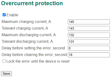
Overcurrent protection settings
In this section:
- Enable – a flag to enable the protection;
- Maximum charging current, А;
- Tolerant charging current, А;
- Maximum discharging current, А;
- Tolerant discharging current, А;
- Delay before setting the error, second;
- Delay before clearing the error, second;
- Lock the error until the device is reset – a flag to block the error until the board is restarted.
As a result of operation of the current protection, the "Overcurrent" error is generated.
Error generation conditions:
- the current is positive (charging), and its modulo value is greater than the “Maximum charging current” value for the “Delay before setting the error” time;
- the current is negative (discharging), and its modulo value is greater than the “Maximum discharging current” value for the “Delay before setting the error” time.
Conditions for removing the error:
- the current is positive (charging) or zero, and its modulo value is less than the “Tolerant charging current” value for the “Delay before clearing the error” time;
- the current is negative (discharging), and its modulo value is less than the “Tolerant discharging current” value for the “Delay before clearing the error” time.
3.6.2 Undervoltage protection
The board implements battery protection from too low or too high voltage on the cells.
To change the battery protection parameters from low voltage on the cells, select the menu "Protections → Undervoltage protection":
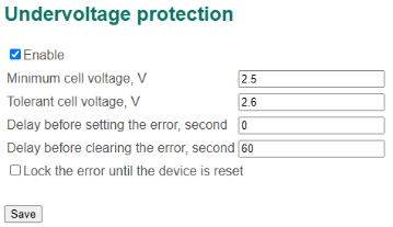
Undervoltage protection settings
In this section:
- Enable – a flag to enable the protection;
- Minimum cell voltage, V;
- Tolerant cell voltage, V;
- Delay before setting the error, second;
- Delay before clearing the error, second;
- Lock the error until the device is reset.
As a result of the operation of battery protection from low voltage, the "Undervoltage" error is generated.
Error generation conditions:
- the minimum voltage among all cells of the battery is less than the “Minimum cell voltage” value for the “Delay before setting the error” time.
Conditions for removing the error:
- the minimum voltage among all cells of the battery is greater than the “Tolerant cell voltage” value for the “Delay before clearing the error” time.
3.6.3 Overvoltage protection
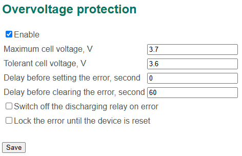
To change the battery protection parameters from high voltage on the cells, select the menu "Protections → Overvoltage protection":
In this section:
- Enable – a flag to enable the protection;
- Maximum cell voltage, V;
- Tolerant cell voltage, V;
- Delay before setting the error, second;
- Delay before clearing the error, second;
- Switch off the discharging relay on error – a flag to open the discharging relay when the "Overvoltage" error is generated;
- Lock the error until the device is reset.
As a result of the operation of the battery protection from high voltage, the "Overvoltage" error is generated.
Error generation conditions:
- the maximum voltage among all cells of the battery is greater than the “Maximum cell voltage” value for the “Delay before setting the error” time.
Conditions for removing the error:
- the maximum voltage among all cells of the battery is less than the “Tolerant cell voltage” value for the “Delay before clearing the error” time.
3.6.4 Low temperature protection
The board implements battery protection from too low temperature.
To change the battery protection parameters from low temperature, select the menu "Protections → Low temperature protection":
In this section:
- Enable – a flag to enable the protection;
- Minimum charging temperature, °C;
- Tolerant charging temperature, °C;
- Minimum discharging temperature, °C;
- Tolerant discharging temperature, °C;
- Delay before setting the error, second;
- Delay before clearing the error, second;
- Lock the error until the device is reset.
As a result of the operation of the battery protection from low temperature, the "Low CH temperature" or “Low DCH temperature” error is generated.
Error generation conditions:
- the minimum temperature among all cells of the battery is less than the “Minimum charging (discharging) temperature” value for the “Delay before setting the error” time.
Conditions for removing the error:
- the minimum temperature among all cells of the battery is greater than the “Tolerant charging (discharging) temperature” value for the “Delay before clearing the error” time.
3.6.5 High temperature protection
The board implements battery protection from too high temperature.
To change the battery protection parameters from high temperature, select the menu "Protections → High temperature protection":
In this section:
- Enable – a flag to enable the protection;
- Maximum charging temperature, °C;
- Tolerant charging temperature, °C;
- Maximum discharging temperature, °C;
- Tolerant discharging temperature, °C;
- Delay before setting the error, second;
- Delay before clearing the error, second;
- Lock the error until the device is reset.
As a result of the operation of the battery protection from high temperature, the "High CH temperature" or “High DCH temperature” error is generated.
Error generation conditions:
- the maximum temperature among all cells of the battery is greater than the “Maximum charging (discharging) temperature” value for the “Delay before setting the error” time.
Conditions for removing the error:
- the maximum temperature among all cells of the battery is less than the “Tolerant charging (discharging) temperature” value for the “Delay before clearing the error” time.
3.6.6 Battery cover protection
To change the protection parameters from opening the battery cover, select the menu "Protections → Battery cover protection":
In this section:
- Enable – a flag to enable the protection;
- Delay before setting the error, second;
- Delay before clearing the error, second;
- Lock the error until the device is reset.
As a result of the operation of the protection against opening the battery cover, the “Battery cover error” is generated.
Error generation conditions:
- there is a signal from the battery cover during the “Delay before setting the error” time.
Conditions for removing the error:
- no signal from the battery cover during the “Delay before clearing the error” time.
3.6.7 High humidity protection
The board can protect the battery from high humidity and water.
To change the protection parameters of the battery from high humidity, select the menu "Protections → High humidity protection":
In this section:
- Enable – a flag to enable the protection;
- Maximum humidty, RH%;
- Tolerant humidty, RH%;
- Delay before setting the error, second;
- Delay before clearing the error, second;
- Lock the error until the device is reset.
As a result of the operation of the battery protection from high humidity, the "High humidity" error is generated.
Error generation conditions:
- the measured humidity is greater than “Maximum humidity” during the “Delay before setting the error” time.
Conditions for removing the error:
- the measured humidity is less than the “Tolerant humidity” during the “Delay before clearing the error” time.
3.6.8 Water protection
To change the protection parameters of the battery from water, select the menu "Protections → Water protection":
In this section:
- Enable – a flag to enable the protection;
- Maximum (water) humidty, RH%;
- Tolerant humidity, RH%;
- Delay before setting the error, second;
- Delay before clearing the error, second;
- Lock the error until the device is reset.
As a result of the operation of the battery protection from water, the "Water" error is generated.
Error generation conditions:
- the measured humidity is greater than the “Maximum (water) humidity” value during the “Delay before setting the error” time.
Conditions for removing the error:
- the measured humidity is less than the “Tolerant humidity” value during the “Delay before clearing the error” time.
3.6.9 Current sensor error
The board is implemented to check the current sensor connection circuits. The circuits are checked for breakage and short-circuit to the +5 V supply line.
To change the test parameters of the current sensor connection circuits, select the menu "Protections → Current sensor error":
In this section:
- Enable – a flag to enable the protection;
- Maximum voltage, V;
- Minimum voltage, V;
- Hysteresis voltage – a hysteresis value to clear the error, V;
- Delay before setting the error, second;
- Delay before clearing the error, second;
- Lock the error until the device is reset.
If there is an open or short circuit connection of a current sensor, the "Current sensor error" is generated.
Error generation conditions:
- the voltage in the signal line or zero level line of the current sensor is greater than the “Maximum voltage” value during the “Delay before setting the error” time;
- the voltage in the signal line or zero level line of the current sensor is less than the “Minimum voltage” value during the “Delay before setting the error” time.
Conditions for removing the error:
- the voltage in the signal line or zero level line of the current sensor is in range from (Minimum voltage + Hysteresis voltage) to (Maximum voltage - Hysteresis voltage) during the “Delay before clearing the error” time.
3.6.10 Short circuit protection
The BMS implements a protection of power circuits (contactors, power cables) against overheating caused by the flow of high current for a long time.
To change the protection parameters from short circuit, select the menu "Protections → Short circuit protection":
In this section:
- Level 1, 2, 3 – three protection levels. The following parameters are configured at each level:
- Enable – a flag to enable the protection;
- Maximum current, A;
- Delay before setting the error, second;
- Delay before clearing the error, second;
- Switch off the charging relay on error – a flag to open the charging relay when the "Short circuit" error occurs;
- Switch off the discharging relay on error – a flag to open the discharging relay when the "Short circuit" error occurs;
- Lock the error until the device is reset.
If there is a short circuit, the "Short circuit" error is generated.
Error generation conditions:
- at any of the three protection levels, the current modulo is greater than the “Maximum current” value during the “Delay before setting the error” time.
Conditions for removing the error:
- the current modulo is lower than the “Maximum current” values for all three protection levels during the “Delay before setting the error” time.
3.6.11 Contactor high temperature protection
The BMS protects power contactors from overheating. To measure the temperature of the contactor, a thermistor is used, connected to the P13 connector of the board. Configuring of the analog input for temperature measurement is described in section Input signals.
To change the overheating protection parameters of power contactors, select the menu "Protections → Contactor high temperature protection":
In this section:
- Enable – a flag to enable the protection;
- Maximum temperature, °C;
- Tolerant temperature, °C;
- Delay before setting the error, second;
- Delay before clearing the error, second;
- Switch off the charging relay on error – a flag to open the charging relay when the "Contactor high temperature" error occurs;
- Switch off the discharging relay on error – a flag to open the discharging relay when the "Contactor high temperature" error occurs;
- Lock the error until the device is reset.
If there is a contactor overheat, the "Contactor high temperature" error is generated.
Error generation conditions:
- the contactor temperature is greater than the “Maximum temperature” value during the “Delay before setting the error” time.
Conditions for removing the error:
- the contactor temperature is lower than the “Tolerant temperature” value during the “Delay before clearing the error” time.
3.6.12 Unallowable charging protection
The BMS can detect that the battery is charging through the discharging circuit and protectively open the discharging relay to prevent unallowable battery operation.
To change the parameters of the unallowable charging protection, select the menu "Protections → Unallowable charging protection":
In this section:
- Enable – a flag to enable the protection;
- Delay before setting the error, second;
- Delay before clearing the error, second;
- Lock the error until the device is reset.
If there is charging the battery through the discharging circuit detected, the "Unallowable charging" error is generated.
Error generation conditions:
- the charging relay is open and the battery current is not zero during the “Delay before setting the error” time.
Conditions for removing the error:
- the battery current is zero during the “Delay before clearing the error” time.
3.6.13 Stuck contactor protection
The BMS Main 2.x protects contactors against sticking.
To change the protection parameters against sticking, select the menu "Protections → Stuck contactor protection":
In this section:
- Enable – a flag to enable the protection;
- Delay before setting the error, second;
- Delay before clearing the error, second;
- Lock the error until the device is reset;
If there is a stuck contactor, the “Stuck contactor” error is generated.
Error generation conditions:
- charging and discharging contactors are open, but the “Charging current present” or “Discharging current present” signal is set.
3.6.14 Contactor feedback check
The BMS Main 2.x can receive feedback signals from contactors and detect discrepancy between the control value and the feedback signal. To enable specific contactor protection, one of the discrete input must be set as corresponding contactor feedback signal (see section Input and output signals).
To change the contactor feedback check parameters, select the menu "Protections → Contactor feedback check":
In this section:
- Enable – a flag to enable the protection;
- Delay before setting the error, second;
- Delay before clearing the error, second;
- Lock the error until the device is reset;
If there is a discrepancy at any contactor, the corresponding contactor feedback error is generated. Error generation conditions:
- discrete output of charging, precharge, discharging, charging/discharging or main contactor not matches its feedback value.
3.6.15 Charging contactor cycles protection
The BMS protects the charging contactor against frequent switching.
To change the protection parameters against high frequency switching of the charging contactor, select the menu "Protections → Charging contactor cycles protection":
In this section:
- Enable – a flag to enable the protection;
- Cycles threshold – a number of cycles in a given period, upon which the “CH contactor cycles error” is generated;
- Period – a time in which the BMS counts switchings of the charging contactor, second;
- Delay before setting the error, second;
- Delay before clearing the error, second;
- Lock the error until the device is reset;
- Cycles – a number of the charging contactor switchings made during battery operation.
If there is the high switching frequency of the charging contactor, the “CH contactor cycles error” is generated.
Error generation conditions:
- the number of switchings of the charging contactor for the “Period” time is greater than or equal to the “Cycles threshold” value. The error is generated with the “Delay before setting the error” delay.
Conditions for removing the error:
- the “Delay before clearing the error” time has passed since the error was generated.
3.6.16 Discharging contactor cycles protection
The BMS protects the discharging contactor against frequent switching.
To change the protection parameters against high frequency switching of the discharging contactor, select the menu "Protections → Discharging contactor cycles protection":
In this section:
- Enable – a flag to enable the protection;
- Cycles threshold – a number of cycles in a given period, upon which the “DCH contactor cycles error” is generated;
- Period – a time in which the BMS counts switchings of the charging contactor, second;
- Delay before setting the error, second;
- Delay before clearing the error, second;
- Lock the error until the device is reset;
- Cycles – a number of the charging contactor switchings made during battery operation.
If there is the high switching frequency of the discharging contactor, the “DCH contactor cycles error” is generated.
Error generation conditions:
- the number of switchings of the discharging contactor for the “Period” time is greater than or equal to the “Cycles threshold” value. The error is generated with the “Delay before setting the error” delay.
Conditions for removing the error:
- the “Delay before clearing the error” time has passed since the error was generated.
3.6.17 Temperature sensor error
The board is implemented to check the temperature sensors connection circuits. The circuits are checked for breakage and short-circuit.
To change the protection parameters of the temperature sensors circuits, select the menu "Protections → Temperature sensor error":
In this section:
- Enable – a flag to enable the protection;
- Delay before setting the error, second;
- Delay before clearing the error, second;
- Lock the error until the device is reset.
If there are no temperature sensors connected to a BMS Logic board or any temperature sensor is shorted, the "No temp. sensors" error and "Temp. sensor is shorted" error are generated respectively. These errors generated and removed with the “Delay before setting the error” and “Delay before clearing the error” delays.
If there is the “No temp. sensors” or “Temp. sensor is shorted” error, the “Critical error” is generated and all relays open.