
3.4.1 Cell defaults
To change the default cell settings, select the menu "Cells → Cell defaults":
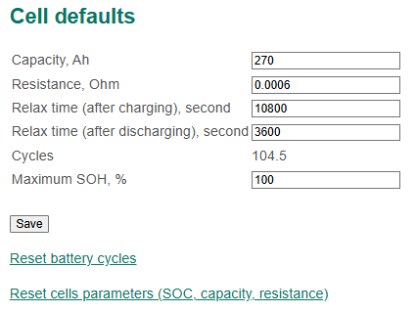
Cell default section
In this section:
- Capacity – nominal capacity of cells, Ah;
- Resistance – nominal (maximum) internal resistance of the cell, Ohm;
- Relax time (after charging) – a relaxation time after charging, second;
- Relax time (atfer discharging) – the relaxation time after discharging, second;
- Cycles – a number of charge-discharge cycles;
- Reset battery cycles – a command to reset charge-discharge cycles;
- Reset cell parameters (SOC, capacity, resistance) – a command to reset cells state of charge, capacity, and resistance.
The values “Capacity”, “Resistance”, “Cycles” are used to calculate the SOC of cells and battery.
The values of “Relax time” are used to determine the state of the battery. If the battery is in a state of relaxation, the system recalculates the voltage on the cells to the state of charge of the battery.
The “Reset cell parameters” command is used for starting-up and adjustment of battery.
3.4.2 SOC estimation
The BMS Main 2.x board calculates the state of charge of the battery (SOC) using two algorithms:
- by open circuit voltage;
- by current and voltage.
It is recommended to use the algorithm of calculation of SOC by voltage and current.
To change the parameters of the algorithm for calculating the battery SOC, select the menu "Cells → SOC estimation":
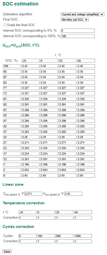
SOC estimation section
In this section:
- Estimation algorithm – SOC calculation algorithm:
- Voltage – by open circuit voltage;
- Current and voltage (simplified);
- Current and voltage (enhanced);
- Final SOC – a method of calculating the battery SOC:
- Minimum cell SOC – the battery SOC is assumed to be equal to the minimum SOC of cells;
- Average cell SOC – the battery SOC is assumed to be equal to the average SOC of cells;
- Scale the final SOC – flag to scale the battery SOC by the following values;
- Internal SOC corresponding to 0% – battery SOC that sets to be 0%;
- Internal SOC corresponding to 100% – battery SOC that sets to be 100%.
- Uocv = Uocv(SOC, t °C) – the dependence of the cell open circuit voltage Uocv on SOC and the cell temperature (selected for specific batteries, can be established experimentally – see section Determining the discharge characteristic);
- Linear zone – linear zone of dependence Uocv = Uocv(SOC, t °C):
- Uocv [point 1] – starting point of the linear zone;
- Uocv [point 2] – end point of the linear zone;
- Temperature correction – the dependence of battery capacity on temperature;
- Cycle correction – the dependence of battery capacity on the number of charge-discharge cycles.
The SOC calculation algorithm for voltage calculates SOC cells based on the tabular dependence Uocv = Uocv(SOC, t °C) .
The SOC calculation algorithm “Current and voltage (simplified)” works as follows:
- if I = 0, the battery is in a state of relaxation and the cell voltage Uocv is outside the [Uocv[point 1]; Uocv[point 2]], the SOC calculation based on the tabular dependence Uocv = Uocv(SOC, t °C);
- in any other cases, the SOC value is proportional to the charge (coulomb) passed through the battery (current time integral).
The SOC calculation algorithm “Current and voltage (enhanced)” differs from the simplified algorithm by online correction of effective capacitance. When using this algorithm, it is necessary to fine tune the tabular dependence Uocv = Uocv (SOC, t °C).
3.4.3 Cell resistance estimation
Calculation of the resistance of cells is carried out in two ways. The first method is used when the battery passes from a relaxation state to a charge or discharge state, wherein the cell resistance value
R = (U-Uocv) / Istable,
where U is the cell voltage measured in the charge or discharge state, V; Uocv is the cell voltage measured in the state of relaxation (before switching to the state of charge or discharge); Istable – stabilized current through the cell in the state of charge or discharge.
The second method is used for a stepwise change in the current through the cell, while the value of the cell resistance:
R = (U2-U1) / (Istable2-Istable1) provided that | Istable2-Istable1 | > 0.2 × Qmax
(Qmax is the maximum cell capacity),
where U2 is the voltage on the cell at the moment when the stabilized current Istable2 is flowing through it; U1 – the voltage on the cell at the moment when the stabilized current Istable1 flowing through it.
The stabilized current Istable = I, if during the stabilization time the instantaneous current I is in the range from 0.95 × I to 1.05 × I.
To change parameters of the algorithm for calculating the cell resistance, select the menu "Cells → Cell resistance estimation":
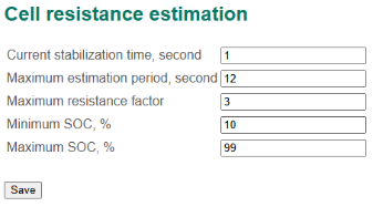
Cell resistance estimation settings
In this section:
- Current stabilization time, second;
- Maximum estimation period – maximum time between resistance measurements. If more time has elapsed since the last determination of the stabilized current Istable than is determined in this field, the resistance calculation is not performed, second;
- Maximum resistance factor – the coefficient of calculation of the maximum acceptable resistance of the cell;
- Minimum SOC – minimum cell SOC value for resistance calculation;
- Maximum SOC – maximum cell SOC value for resistance calculation.
The calculated resistance is accepted by the system as valid (and therefore updated) if its value is in the range from Resistance/2 to “Maximum resistance factor” × Resistance, where "Resistance" is the nominal resistance of the cell (see section Cell defaults). If the calculated resistance value is greater than the value (Maximum resistance factor × Resistance), the updated resistance value will be equal to the value (Maximum resistance factor × Resistance).
3.4.4 Cell balancing
The BMS Main 2.x supports two cell balancing algorithms:
- balancing stacks individually;
- balancing the entire battery (used by default).
Balancing stacks individually balances the voltage within a group of cells that are connected to the same BMS Logic board. It is not recommended to use this algorithm in typical battery designs.
Balancing the entire battery makes the voltage of all cells be equal to the minimum cell voltage.
The following balancing rules are supported:
- only when the battery is charging (current I > 0);
- when the battery is charging (current I > 0) or when the battery is in a state of relaxation;
- always (regardless of battery state).
A balancing resistor is connected to the cell if:
- the voltage on the cell is higher than the starting voltage of the balancing;
- the difference between the cell voltage and the minimum voltage among the cells of the battery is greater than the balancing threshold.
If the BMS Logic board overheats, then the balancing of the cells connected to this board will not be performed (see Logic high temperature protection).
To change the cell balancing parameters, select the menu "Cell → Cell balancing":
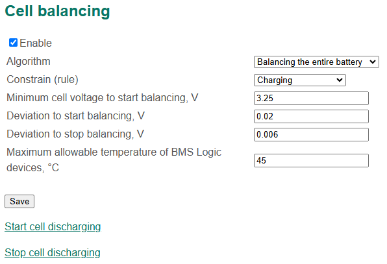
Cell balancing settings
In this section:
- Enable – a flag to enable cell balancing;
- Algorithm – a balancing algorithm:
- Balancing stacks individually;
- Balancing the entire battery;
- Constrain (rule):
- Charging;
- Charging or relaxed;
- Always (regardless of battery state);
- Minimum cell voltage to start balancing, V;
- Balancing threshold, V;
- Start cell discharging – a command to start forced balancing of all battery cells (used for service purposes);
- Stop cell discharging – a command to stop forced balancing of all battery cells (used for service purposes).
3.4.5 Series balancing
The BMS Main 2.x board supports work with two independent (galvanically unrelated) cell series. To monitor the status of two series, two current sensors are used: primary and secondary (AUX). A series of cells must be equivalent: they must have the same number of cells and the same capacity.
Since the series of cells can operate at different loads, they must be balanced. For this, the BMS Main 2.x provides two relays: “Balancing series 1” and “Balancing series 2” (see section Configuration of output discrete signals and relays), as well as a combined algorithm that considers both the voltage of each series and the charge that these series gave load. “Balancing series 1” and “Balancing series 2” relays are used to connect high-power balancing resistors in parallel with cells series 1 and 2.
When charging the battery, balancing is performed based on the voltage of the series. A balancing resistor is connected to the cell series if:
- the series voltage is higher than the starting voltage of the balancing;
- the difference between the voltage of a series of cells and the minimum voltage among the battery series is greater than the balancing threshold.
When the battery is discharging (work on load), balancing is turned on if one of the series gives the load a charge (Ah), which is more by the amount Qthr of the charge given off by another series.
To change the series balancing parameters, select the menu "Cell → Series balancing":
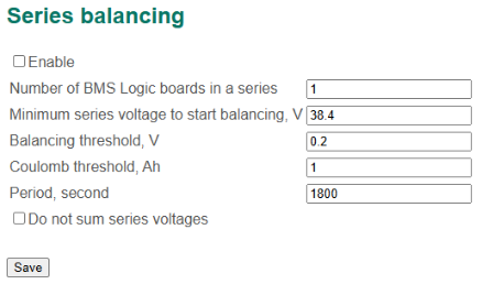
Series balancing settings
In this section:
- Enable – a flag to enable series balancing;
- Number of BMS Logic boards in a series;
- Minimum series voltage to start balancing, V;
- Balancing threshold, V;
- Coulomb threshold – the difference of the charges Qthr, given by a series of cells, above which balancing to be started, Ah;
- Period – period to reset of charge counters for each series (to avoid accumulation of error), second.
3.4.6 Cell analysis
Discharge characteristics of the battery – the dependence Uocv = Uocv (DOD) – is used to determine the tabular dependence Uocv = Uocv (SOC, t °C) (see section Calculating the state of charge (SOC)), which is necessary for calculating the state of charge of the battery.
The BMS Main 2.x board can automatically determine the battery discharge characteristic.
Before starting the process of determining the discharge characteristic, it is necessary to prepare a BMS:
- Charge the battery.
- Connect a contactor to the discharging relay which switches the resistive load to the battery.
- Connect a resistive load to the contactor, which will provide a discharge current of 0.5C (where C is the cell capacitance).
To configure parameters for determining the discharge characteristic of the battery, select the menu "Cells → Cell analysis":

Cell analysis section
In this section:
- Enable – a flag to enable cell analysis;
- Discharge step, Ah;
- Delta voltage – a maximum allowable voltage drop for the cell, V;
- Logic index – an address of the BMS Logic board to which the analyzed cell is connected;
- Cell index – a position of the analyzed cell connected to the BMS Logic board;
- Analyse cell with minimum voltage – a flag to analyse of the least charged cell (in this case, the values of Logic index and Cell index are ignored).
Discharge step should be set equal to
Discharge step = С/21,
where C is the cell capacity.
The discharge characteristic will be constructed for the given cell (its position is determined by the fields Logic index and Cell index).
The algorithm for determining the discharge characteristic of the battery will be started if the Enable flag is set. From this moment, the control of the discharge relay is performed by this algorithm.
Algorithm steps:
- DOD = 0.
- Disconnecting the discharge relay.
- Waiting for the relaxation of the battery.
- Measuring Uocv = U.
- Saving the point of the discharge characteristic (Q, UOCV).
- Activation of the discharge relay. DOD1 = DOD + Discharge step, U1 = U
- If DOD = DOD1 or U < (U1 – Delta voltage), then go to step 2.
- If the "Undervoltage" error is detected, then the end of the algorithm.
During the operation of the algorithm, a file with the name "CELLANALYSIS.TXT" in the CSV format will be created on the SD card.
File structure:
| Time | DOD | Logic | Cell | OCV | Resistance |
| 10.11.2017 12:28:34 | 0.0 | 1 | 1 | 4.180 | 0.080000 |
| ... | ... | … | … | ... | ... |
Parameter names:
- Time – date and time;
- DOD – depth of discharge, Ah;
- Logic – the address of the BMS Logic board to which the analyzed cell is connected;
- Cell – position of the analyzed cell for which OCV and Resistance values are provided;
- OCV – cell voltage Uocv, V;
- Resistance – cell resistance, Ohm.
SOC correction
The BMS Main 2.x board can recalculate the battery SOC after long-term storage or after long-term working in the case when the battery was not charged fully or discharged totally. Recalculation is done based on the tabular dependency Uocv = Uocv (SOC, t) (see section Calculating the state of charge (SOC)).
To configure parameters for periodically correcting the battery state of charge, select the menu "Cells → SOC correction":
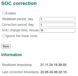
SOC correction settings
In this section:
- Enable – a flag to enable SOC correction;
- Shutdown period – a time the battery is off, day. If the BMS detects on its startup that it was off during the “Shutdown period” time, the BMS recalculates the battery state of charge base on the tabular dependency Uocv = Uocv (SOC, t);
- Correction period – a period of correcting the battery SOC, day. If the BMS detects that the last correction was more than the “Correction period” ago, the BMS recalculates the battery state of charge base on the tabular dependency Uocv = Uocv (SOC, t) and tunes it gradually during the “SOC change time”;
- SOC change time – a duration of the linear changing the battery SOC to the value calculated by the correction algorithm, minute.