
3.3.1 Input signals
The BMS Main 2.x board has 4 discrete inputs of the "dry contact" type. For each discrete input, its purpose and the inversion requirement are specified.
BMS Main 2.x board has 4 analog inputs for connecting current, temperature and humidity sensors.
The order of the numbering of the discrete and analog inputs corresponds to the order of the numbering on the board.
To configure the input discrete and analog signals, select the menu "Signals → Input signals":
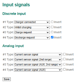
Discrete inputs in this section:
- No input;
- Battery cover – a signal from the battery cover trailer;
- Charger connected – a signal from the charger connector;
- Power up/down request – a signal from the external power monitor which is used for proper powering BMS up or down;
- Inhibit charging – a command to open the charging relay;
- Inhibit discharging – a command to open the discharging relay;
- CH contactor feedback – a feedback signal from the charging contactor;
- DCH contactor feedback – a feedback signal from the discharging contactor;
- Insulation status – a signal from an external insulation monitoring device;
- Charge request – a request for closing the charging contactor;
- Precharge request – a request for closing the precharging contactor;
- Discharge request – a request for closing the discharging contactor;
- PCH contactor feedback – a feedback signal from the precharging contactor;
- CH/DCH contactor feedback – a feedback signal from the charging/discharging contactor;
- Main contactor feedback – a feedback signal from the main contactor.
If the "Signal from the battery cover" assignment is selected, the discrete input is used to monitor the state of the battery cover (see 3.6.6 Battery cover protection).
if the "Charger connected" assignment is selected, the discrete input is involved in the algorithms of charge and discharge control (see 3.5.1 Charge control and 3.5.2 Discharge control).
If the "Power up/down request" assignment is selected, the discrete input is involved in the algorithms of opening the charging and discharging relays and sending acknowledgment of power down to the external equipment (see 3.5.1 Charge control and 3.5.2 Discharge control).
If the “Inhibit charging” assignment is selected, the discrete input is used to open the charging relay.
If the “Inhibit discharging” assignment is selected, the discrete input is used to open the discharging relay.
If the “CH contactor feedback”, “DCH contactor feedback”, “PCH contactor feedback”, “CH/DCH contactor feedback” or “Main contactor feedback” assignment is selected, the discrete input is involved in monitoring the corresponding contactor’s feedback signal (see 3.6.14 Contactor feedback check).
If the “Charge request”, “Precharge request” or “Discharge request” assignment is selected, the discrete input is used to control opening the corresponding contactor (see 3.5.1 Charge control and 3.5.2 Discharge control).
If the “Insulation status” assignment is selected, the discrete input is used to monitor a signal from an external insulation monitoring device (see 3.6.23 Insulation monitoring).
Analog inputs in this section:
- No input;
- Current sensor;
- Current zero level;
- Temperature sensor;
- Humidity sensor;
- Current sensor (AUX) – additional current sensor for measuring current in a series of cells;
- Current zero level (AUX) – zero level bus for additional current sensor.
Assignment of analog inputs must be selected as follows:
- Analog Input #1 – Current sensor;
- Analog Input #2 – No input / Current sensor reference line / Current sensor (2nd range) (see note);
- Analog Input #3 – No input / Temperature sensor / Current sensor (AUX);
- Analog Input #4 – No input / Humidity sensor / Current reference line (AUX) / Current sensor (2nd range) (AUX).
3.3.2 Current sensor
After selecting the assignment of the analog inputs, you need to configure the parameters of the sensors connected to the board.
To configure the current sensor parameters, select the menu "Signals → Current sensor":

In the «Primary sensor» и «Auxiliary sensor» sections:
- Sensor type – drop-down menu with supported sensor types;
- Nominal current – rated current of the sensor according to the datasheet, А;
- Sensitivity – sensitivity of the current sensor according to the datasheet, V / Inominal.;
- Zero level – level "0A" of the current sensor, V;
- Multiply the charging current (experimental) – experimental flag for scaling the charging current by given multiplier;
- Multiplier – charging current multiplier;
In the «Options» section:
- Calibrate sensor on startup – calibration flag (zero level setting) of the current sensor when the board is started;
- Calibration time – calibration time of the current sensor, second;
- System consumption (current offset) – consumption of the BMS system from the battery, A; This setting is used to adjust the current sensor;
- Set sensor zero level – command set the zero level of the current sensor (used for service purposes).
Calibration of the current sensor (“Calibrate sensor on startup” flag) is necessary if the sensor does not have a reference line (zero level signal).
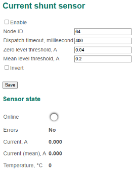
3.3.3 Current shunt sensor
To configure the shunt current sensor parameters, select the menu "Signals → Current shunt sensor":
In this section:
- Settings:
- Enable – a flag to start interaction with BMS Current Sensor (if interaction is enabled then BMS doesn’t use Hall-Effect current sensor which settings are described in the menu "Signals → Current sensor");
- Node ID – an address of BMS Current Sensor in CANopen network;
- Dispatch timeout – timeout of dispatching packages from BMS Current Sensor (if no data is being received from current sensor during this time, the “Shunt offline” flag is set), millisecond;
- Zero level threshold – T0 level, A (if module of instantaneous current (II) which is received from shunt sensor is lower than T0, BMS will assume that current flowing through the battery is zero);
- Mean level threshold – TM level, A (if module of instantaneous current (II) which is received from shunt sensor is between TM and T0, BMS will use mean value of current IM; if II is greater than TM, BMS will use instantaneous value of current II);
- Invert – a flag to invert current values;
- Sensor state:
- Online – a flag showing that the communication with the BMS Current Sensor is established;
- Errors – a list of internal errors of the shunt sensor;
- Current – an instantaneous value of current measured by the BMS Current Sensor, A (measuring frequency is 50 Hz);
- Current (mean) – a mean value of current measured by the BMS Current Sensor, A (the value is calculated as an average of 100 consistent measurements);
- Temperature – a temperature of the shunt sensor, °C.
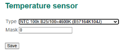
3.3.4 Temperature sensor
To configure the temperature sensor parameters, select the menu "Signals → Temperature sensor":
In this section:
- Type – type of temperature sensors.
- Mask -
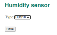
3.3.5 Humidity sensor
To set the humidity sensor parameters, select the menu "Signals → Humidity sensor":
In this section:
- Type – type of the humidity sensor.
3.3.6 Output signals
The BMS Main 2.x board has 4 discrete outputs. For each discrete output, its purpose and inversion requirement are specified.
The BMS Main 2.x board has 4 solid-state relays (#1 and #2 of them are bipolar, and the #3 and #4 are unipolar). For each relay, its purpose and inversion requirement are specified.
The order of the numbering of the discrete outputs and the relay corresponds to the order of the numbering on the board.
To configure output discrete signals and relays, select the menu "Signals → Output signals":
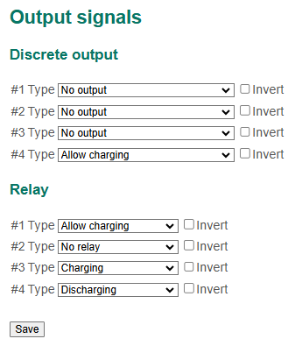
Discrete outputs in this section:
- No output;
- Low SOC;
- High charging current;
- Cooler;
- Heater;
- Allow charging;
- Precharging;
- Acknowledgement of power down;
- Power up;
If the "Low SOC" assignment is selected, the output indicates the low battery charge level (see 3.6.26 Low SOC signal).
If the "High battery charge current" assignment is selected, the output indicates that the charging current exceeds the predefined value (see 3.6.27 High charging current signal).
If the "Cooler" assignment is selected, the output indicates the overheating of the battery (see 3.6.5 High temperature protection).
If the "Heater" assignment is selected, the output indicates the low battery temperature signal (see 3.6.4 Low temperature protection).
If the "Allow charging" assignment is selected, the output is used to give the charger the allowance to charge the battery (see 3.5.1 Charge control).
If the "Precharging" assignment is selected, the output is used to charge the capacitive load (see 3.5.2 Discharge control).
If the "Acknowledgement of power down" assignment is selected, the output is used to acknowledge power down of the BMS. Acknowledgement is outputted when the charge and discharge relays have been opened on power down request (see 3.5.1 Charge control and 3.5.2 Discharge control).
If the "Power up" assignment is selected, the output is used to indicate the power status of BMS (see 3.5.6 Power down control).
Relay assignments in this section:
- No relay;
- Charging;
- Discharging;
- Allow charging;
- Cooler;
- Heater;
- Precharging;
- Balancing series 1;
- Balancing series 2;
- Discharging (AUX);
- Main contactor;
- Power up.
If the "Charging" assignment is selected, the relay is used to charge the battery (see 3.5.1 Charge control).
If the "Discharging" assignment is selected, the relay is used to connect battery to the load (see 3.5.2 Discharge control).
If the "Allow charging" assignment is selected, the relay is used to give the charger an allowance to charge the battery (see 3.5.1 Charge control).
If the "Cooler" assignment is selected, the relay receives a signal indicating overheating of the battery (see 3.6.5 High temperature protection) or the signal "Cooler" (see 3.6.30 Cooler control).
If the "Heater" assignment is selected, a low battery temperature signal is outputted to the relay (see 3.6.4 Low temperature protection) or a signal "Heater" (see 3.6.28 Heater control).
If the "Precharging" assignment is selected, the relay is used to charge the capacitive load (see 3.5.2 Discharge control).
If the "Balancing series 1" assignment is selected, the relay is used to connect a balancing resistor to the cell series 1 (see 3.4.5 Series balancing).
If the "Balancing series 2" assignment is selected, the relay is used to connect a balancing resistor to the cell series 2 (see 3.4.5 Series balancing).
If the "Discharging (AUX)" assignment is selected, the relay is used to power external equipment (see 3.5.3 Discharging (AUX) control).
If the "Main contactor" assignment is selected, the relay is used to close the main contactor in the common (minus) power bus.
If the "Power up" assignment is selected, the relay is used to close the contactor in the BMS Main power bus.