

3. Configuration
Configuration
Connecting device to PC
To connect the BMS Logic 2R to a PC, use the BMS USB-RS485 adapter. It allows to power and communicate with the BMS Logic 2R:
- Connect the BMS USB-RS485 to the BMS Logic 2R:
a) the communication circuits (X3 -> X3);
b) the circuits of cells (X5 -> X1). - Connect the BMS USB-RS485 to a PC using a mini-USB or USB-C cable.
- Turn all the BMS USB-RS485’s switches to the “I” position.
The assembly drawings of the harnesses between the BMS USB-RS485 and BMS Logic 2R are given below.
Communication and power cable
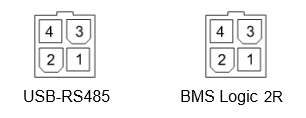
The wires of the communication and power cable must be connected according to the following table:
| Circuit name | Pin of the connector to BMS USB-RS485 | Pin of the connector to BMS Logic 2R |
| RS485_A | 1 | 2 |
| RS485_B | 2 | 1 |
| +5V | 3 | 4 |
| GND | 4 | 3 |
Cells cable
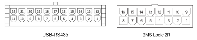 The wires of the cells cable must be connected according to the following table:
| Circuit name | Pin of the connector to BMS USB-RS485 | Pin of the connector to BMS Logic 2R |
| V- | 1 | 9 |
| C1 | 13 | 8 |
| C2 | 2 | 16 |
| C3 | 14 | 7 |
| C4 | 3 | 15 |
| C5 | 15 | 6 |
| C6 | 4 | 14 |
| C7 | 5 | 5 |
| C8 | 6 | 13 |
| C9 | 7 | 4 |
| C10 | 8 | 12 |
| C11 | 9 | 3 |
| C12 | 10 | 11 |
Setting device address
The address is set by the SWD1 switch. Address 0 (all switches are raised) is incorrect and will force the device to go to bootloader.
The address from 1 to 20 is set on the switches as a binary number. The ON state (bottom position) corresponds to a single digit value. The switch with the number 1 corresponds to the lower order. The address is read by the device at initialization, so to change the address it is necessary to switch off and turn on the device.
To select the proper device address, use the following table:
| Address | SWD1 | |||||
| 1 | 2 | 3 | 4 | 5 | 6 | |
| 1 | ON | OFF | OFF | OFF | OFF | OFF |
| 2 | OFF | ON | OFF | OFF | OFF | OFF |
| 3 | ON | ON | OFF | OFF | OFF | OFF |
| 4 | OFF | OFF | ON | OFF | OFF | OFF |
| 5 | ON | OFF | ON | OFF | OFF | OFF |
| 6 | OFF | ON | ON | OFF | OFF | OFF |
| 7 | ON | ON | ON | OFF | OFF | OFF |
| 8 | OFF | OFF | OFF | ON | OFF | OFF |
| 9 | ON | OFF | OFF | ON | OFF | OFF |
| 10 | OFF | ON | OFF | ON | OFF | OFF |
| 11 | ON | ON | OFF | ON | OFF | OFF |
| 12 | OFF | OFF | ON | ON | OFF | OFF |
| 13 | ON | OFF | ON | ON | OFF | OFF |
| 14 | OFF | ON | ON | ON | OFF | OFF |
| 15 | ON | ON | ON | ON | OFF | OFF |
| 16 | OFF | OFF | OFF | OFF | ON | OFF |
| 17 | ON | OFF | OFF | OFF | ON | OFF |
| 18 | OFF | ON | OFF | OFF | ON | OFF |
| 19 | ON | ON | OFF | OFF | ON | OFF |
| 20 | OFF | OFF | ON | OFF | ON | OFF |
Address selection requirements:
- it is necessary to use consecutive addresses, without omissions;
- it is necessary to use addresses from 1 to 20;
- when choosing an address, follow the rule: a device with a smaller address serves less potential;
- to facilitate subsequent maintenance, it is recommended to create a schematic indicating the location of the BMS Logic 2R and their addresses.