
2. Установка и подключение
Установка и подключение
Порядок установки
Место установки устройства BMS Logic 2.0 должно быть защищено от попадания механических объектов (пыли, грязи, крупных объектов) и воды. Устройства BMS Logic 2.0 рекомендуется располагать вблизи ячеек, которые они контролируют, но вдали от цепей высокого тока для уменьшения наводок на измерительные цепи и увеличения общей надёжности батарейной системы.
Место установки должно предполагать удобный доступ к устройству для его последующего подключения.
Устройство BMS Logic 2.0 поставляется в сборе с радиатором для рассеивания тепла, выделяющегося при балансировке ячеек. При использовании устройства в закрытых корпусах необходимо обеспечить съём тепла с радиатора, в противном случае это может привести к повреждению устройства.
Габаритные и установочные размеры приводятся на рисунке ниже.

| Параметр | Значение |
Габаритные размеры BMS Logic 2.0 (длина × ширина × высота), мм | 125 × 84 × 25 |
| Установочные размеры BMS Logic 2.0 (длина × ширина), мм | 115 × 50 |
| Установочные отверстия BMS Logic 2.0 | M4 |
| Тип разъемов X1-X3 | Molex серия Mini-Fit |
Разъёмы
Устройство BMS Logic 2.0 предназначено для измерения температуры (на серию из 12 ячеек приходится 2 датчика температуры) и напряжения 12 ячеек. Устройство также выполняет пассивную балансировку ячеек.

X1 – header for cells and temperature sensors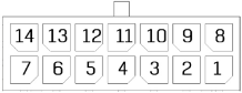
| Pin | Name | Description |
| 1 | TEMP2 | Signal from the thermistor #2 |
| 2 | TEMPC | Ground of the thermistors |
| 3 | C11 | Cell #11 |
| 4 | C9 | Cell #9 |
| 5 | C7 | Cell #7 |
| 6 | C5 | Cell #5 |
| 7 | C3 | Cell #3 |
| 8 | C1 | Cell #1 (minimum potential with respect to V-) |
| 9 | V- | Minus of the cell stack |
| 10 | TEMP1 | Signal from the thermistor #1 |
| 11 | C12 | Cell #12 (maximum potential of the cell stack) |
| 12 | C10 | Cell #10 |
| 13 | C8 | Cell #8 |
| 14 | C6 | Cell #6 |
| 15 | C4 | Cell #4 |
| 16 | C2 | Cell #2 |
X2, X3 – headers for communication with BMS Main

| Pin | Name | Description |
| 1 | RS485_A | RS-485 line A for communication with the BMS Main |
| 2 | RS485_B | RS-485 line B for communication with the BMS Main |
| 3 | +5V | Supply voltage 5V |
| 4 | GND | Ground |
Switches and indicators
SWD1 – address switch
| Switch number | Description |
| 1 | The first (the lowest) bit of the address. Position ON - bit is 1 |
| 2 | The second bit is the address. Position ON - bit is 1 |
| 3 | The third bit of the address. Position ON - bit is 1 |
| 4 | The fourth bit of the address. Position ON - bit is 1 |
| 5 | The fifth bit of the address. Position ON - bit is 1 |
| 6 | The sixth (the highest) bit of the address. Position ON - bit is 1 |
DS1 – mode indicator
| State | Description |
| Blinking | Communication between the BMS Main and the device is established |
| No light | There is no communication between the BMS Main and the device |
Connection procedure
Connection to BMS Main
To connect the BMS Main to BMS Logic 2.0 do the following steps:
- Connect the BMS Main to the first BMS Logic 2.0 (P15 -> X3).
- Connect the BMS Logic 2.0 to each other (X2 -> X3).
- Install jumper P1 on the last BMS Logic 2.0 in the chain.
Connecting battery cells
To connect the battery cells, follow the picture below. Incorrect connection of the cells can damage the BMS Logic 2.0.
Begin the connection with the negative of the battery: the "V-" of the first BMS Logic 2.0 is connected to "B-", then the first cell (C1) of the battery is connected, then the second (C2), etc. The “V-“ of the next BMS Logic 2.0 is connected to the C12 of the previous BMS Logic 2.0. If not all inputs of the cells are used, then the remaining inputs are connected to the cell with the highest potential.

Connecting thermistors
Thermistors should be fastened to the cells, excluding short circuits to the cell terminals (for example, isolate thermistors with heat shrink). For reliable operation, it is recommended to use all thermistors (1 temperature sensor for 6 cells).
