Connection
Installation
The mounting location must be protected from mechanical obstacles (dust, dirt, large objects) and water. Device placement should provide easy access for connection.
| Parameter | Value |
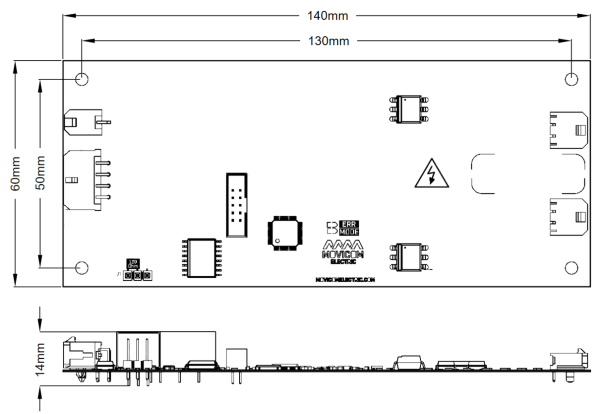
| Overall dimensions (length × width × height), mm | 140 × 60 × 14 |
| Mounting dimensions (length × width), mm | 130 × 50 |
| Mounting holes | M3 |
Headers
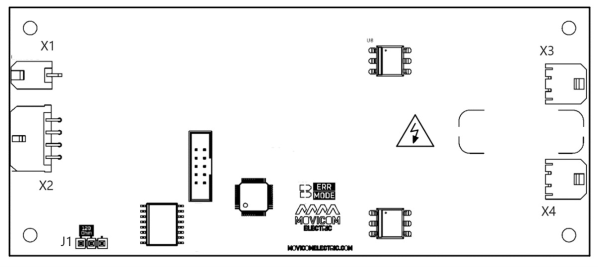
The BMS IMD has two headers for connecting the power line (X3 and X4), a header for connecting external equipment and power supply (X2), a chassis connection header (X1) and a jumper which connects a terminal resistor to the CAN bus (J1).
X1 – header for chassis connection
Receptacle Housing: Molex 430250200. Terminals: Molex 43030

| Pin | Name | Description |
| 1 | CHASSIS | Vehicle chassis connection |
| 2 | CHASSIS | Vehicle chassis connection |
X2 – header for a top-level controller (rev1.1 only)
Receptacle Housing: Molex 430250800. Terminals: Molex 43030
| Pin | Name | Description |
| 1 | GND | Ground |
| 2 | CAN_H | CAN H line for communication with external equipment |
| 3 | GND | Ground |
| 4 | GND | Ground |
| 5 | V+ | Device supply line (9-32V) |
| 6 | CAN_L | CAN L line for communication with external equipment |
| 7 | OUT_WORK | Discrete output for work indication (open drain, max 60V, 1A) |
| 8 | OUT_ERROR | Discrete output for error indication (open drain, max 60V, 1A) |
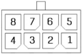
X2 – header for a top-level controller (rev1.2 only)
Receptacle Housing: Molex 430251200. Terminals: Molex 43030
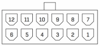
| Pin | Name | Description |
| 1 | GND | Ground |
| 2 | CAN_H | CAN H line for communication with external equipment |
| 3 | GND | Ground |
| 4 | GND | Ground |
| 5 | GND | Ground |
| 6 | GND | Ground |
| 7 | V+ | Device supply line (9-32V) |
| 8 | CAN_L | CAN L line for communication with external equipment |
| 9 | OUT_WORK | Discrete output for work indication (open drain, max 42V, 1A) |
| 10 | OUT_ERROR | Discrete output for error indication (open drain, max 42V, 1A) |
| 11 | KEYRUN_1 | Device power on signal |
| 12 | KEYRUN_2 | Device power on signal |
X3 – header for positive line connection
Receptacle Housing: Molex 436450200. Terminals: Molex 43030

| Pin | Name | Description |
| 1 | LINE+ | Positive line |
| 2 | LINE+ | Positive line |
X4 – header for negative line connection
Receptacle Housing: Molex 436450200. Terminals: Molex 43030
| Pin | Name | Description |
| 1 | LINE- | Negative line |
| 2 | LINE- | Negative line |
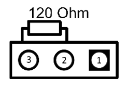
J1 – CAN terminal resistor jumper
To connect the terminal resistor between the CANH and CANL lines, install jumper on pins 2 and 3 like shown on the picture below.