

2. Installation and connection
Last modified by Admin on 2025/03/18 12:35
Installation and connection
Safety rules
Before use, configure the system. Proper operation of the device is possible only if it is correctly configured.
Installation
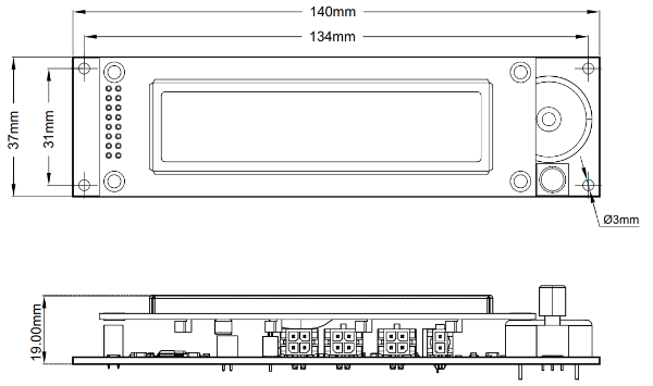
| Parameter | Value |
| Overall dimensions (length × width × height), mm | 140 × 37 × 23 |
| Mounting dimensions (length × width), mm | 134 × 31 |
| Mounting holes | M3 |
Headers
The BMS Display has three headers for connecting the BMS (P3, P4 и P5), a header for an external button (P6) and a switch which connects a terminal resistor to the CAN bus (SWD1).
P3, P4 and P5 – headers for communication with BMS
Receptacle Housing: Molex 430250400. Terminals: Molex 43030

| Pin | Name | Description |
| 1 | CANH | CAN H line for communication with the BMS controller |
| 2 | CANL | CAN L line for communication with the BMS controller |
| 3 | +5V | Supply voltage 5V |
| 4 | GND | Ground |
P6 – header for external button
Receptacle Housing: Molex 430250200. Terminals: Molex 43030

| Pin | Name | Description |
| 1 | BTN1 | Button line (dry contact) |
| 2 | BTN2 | Button line (dry contact) |
SWD1 - CAN terminal resistor switch
To connect the terminal resistor between the CANH and CANL lines, switch the SWD1 to the ON position.