
Applications
Navigation
Table of Contents
- 2 Installation and connection
- 2.1 Safety rules
- 2.2 Installation procedure
- 2.3 Headers
- 2.3.1 X1 – header to power the device
- 2.3.2 X2 – header for contactors
- 2.3.3 X3 – header for discrete inputs and outputs
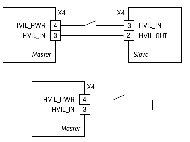
- 2.3.4 X4 – header for HVIL
- 2.3.5 X5 – header for current and temperature sensors
- 2.3.6 X6 – header for CAN1 and RS-485-1 (external buses
- 2.3.7 X7 – header for CAN2 (internal bus
- 2.3.8 X8 – header for CAN3
- 2.3.9 X9 – header for BMS Logic (RS-485-2
- 2.3.10 X10 – miniUSB connector
- 2.3.11 X11 – header for high-voltage bus before contactors (plus
- 2.3.12 X12 – header for high-voltage bus before contactors (minus
- 2.3.13 X13 – header for high-voltage bus after contactors (plus
- 2.3.14 X14 – header for high-voltage bus after contactors (minus
- 2.3.15 J1 – jumper for switching RS-485-1 bus terminal resistor
- 2.3.16 J2 – jumper for switching CAN1 bus terminal resistor
- 2.3.17 J3 – jumper for switching CAN2 bus terminal resistor
- 2.3.18 J5, J6 – jumpers for emergency opening of contactors when removing discrete input signals DIN7, DIN8
- 2.4 Indicators
- 2.4.1 DS1 – LED indicating device power
- 2.4.2 DS2 – LED indicating device work
- 2.4.3 DS3 – LED indicating interaction with child devices
- 2.4.4 DS4 – LED indicating loss of connection with child devices
- 2.4.5 DS5-DS10 – LEDs indicating contactor switches 1-6
- 2.4.6 DS11 – LED indicating the presence of power supply for contactors
- 2.5 Connection procedure