Skip to Content
Home Logo of the wiki
  • Log-in
    • XWikiGuest

    • Docs
    • Page Index
    • User Index

    • Global
    • Languages
      • English
      • Русский
    • What's New

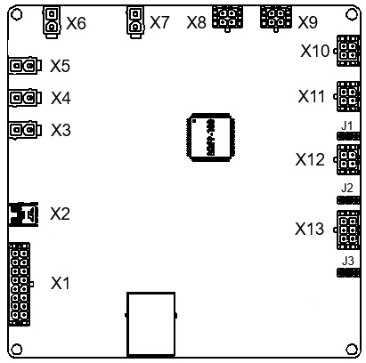
The available versions of attachment '1774455018488-627.png' are:

VersionSize AuthorDate
1774455018488-627.png 1.1 36445 Admin 2026/03/25 16:10
1774455018488-627.png 1.2 0 Admin 2026/03/25 16:30

Applications

  • File Manager

Navigation

Table of Contents

  • 2 Installation and connection
    • 2.1 Safety rules
    • 2.2 Installation procedure
    • 2.3 Headers
      • 2.3.1 X1 – header for discrete inputs and outputs
      • 2.3.2 X2 – miniUSB connector
      • 2.3.3 ​X3 – header for power supply
      • 2.3.4 X4, X5, X6, X7 – header of relay 1, 2, 3 and 4
      • 2.3.5 X8 – header for current sensor 1
      • 2.3.6 X9 – header for current sensor 2
      • 2.3.7 X10 – header for temperature sensors
      • 2.3.8 X11 – header for BMS Logic
      • 2.3.9 X12 – header for CAN2 interface
      • 2.3.10 X13 – header for CAN1 and RS-485 interfaces
      • 2.3.11 J1 – jumper for switching CAN2 bus terminal resistor
      • 2.3.12 J2 – jumper for switching RS-485-1 bus terminal resistor
      • 2.3.13 J3 – jumper for switching CAN1 bus terminal resistor
    • 2.4 Indicators
      • 2.4.1 DS2 – operation indicator
      • 2.4.2 DS3 – communication indicator
      • 2.4.3 DS4 – error indicator
      • 2.4.4 DS1.1-DS1.4 – relay 1-4 indicator
    • 2.5 Connection procedure
© 2024-2026, Movicom Electric