2. Installation and connection
Installation and connection
Safety rules
To perform the protection functions, the BMS must be able to disconnect the battery from the load and charger. To do this, at least one contactor able to break the load and charge circuits must be connected to the BMS.
Before use, configure the system. Proper operation of the BMS is possible only if it is correctly configured.
It is not recommended to use the system in batteries formed by several series of cells connected in parallel. To increase capacity, it is recommended to connect several cells in parallel groups, and then connect the groups in series.
Installation procedure
The mounting area of the BMS Mini must be protected from mechanical particles (dust, dirt, large objects) and water. The BMS Mini is recommended to be placed close to the cells it controls, but away from high current circuits to reduce interference to measuring circuits and increase overall reliability of installation.
The installation site must provide convenient access for subsequent connection to the device’s headers for connecting other system elements: a current sensor, contactors, display panels.
The BMS Mini has a heat sink to dissipate the heat generated during the balancing of the cells. When used in enclosed enclosures, heat must be removed from the sink, otherwise it may damage the device.
Overall and mounting dimensions of the BMS Mini are shown on figures below.


Parameter | Value |
Overall dimensions (length × width × height), mm | 139.5 × 117 × 17 |
| Mounting dimensions (length × width), mm | 130 × 111 |
| Mounting holes | M3 |
Headers
There are names and locations of the BMS Mini headers on figure below.

Х1 – header for contactors
Receptacle Housing: Molex 430251800. Terminals: Molex 43030

| Pin | Name | Description |
| 1 | - | - |
| 2 | +12V | Supply voltage from the internal 12V DC/DC converter |
| 3 | GND | Ground |
| 4 | +12V | Supply voltage from the internal 12V DC/DC converter |
| 5 | GND | Ground |
| 6 | +12V | Supply voltage from the internal 12V DC/DC converter |
| 7 | GND | Ground |
| 8 | +12V | Supply voltage from the internal 12V DC/DC converter |
| 9 | GND | Ground |
| 10 | - | - |
| 11 | FB1 | Feedback signal from contactor 1 |
| 12 | OUT1 | Contactor control 1 (low side switch), 100V, max 5A |
| 13 | FB2 | Feedback signal from contactor 2 |
| 14 | OUT2 | Contactor control 2 (low side switch), 100V, max 5A |
| 15 | FB3 | Feedback signal from contactor 3 |
| 16 | OUT3 | Contactor control 3 (low side switch), 100V, max 5A |
| 17 | FB4 | Feedback signal from contactor 4 |
| 18 | OUT4 | Contactor control 4 (low side switch), 100V, max 5A |

X2 – mini-USB connector.
Mini-USB connector is used for configuring the BMS via ElectricDeviceMonitor.
X3 – header for discrete inputs and outputs signals
Receptacle Housing: Molex 430251600. Terminals: Molex 43030

| Pin | Name | Description |
| 1 | DIN1 | Discrete input 1 “dry contact” (+5V) |
| 2 | DIN2 | Discrete input 2 “dry contact” (+5V) |
| 3 | DIN3 | Discrete input 3 “dry contact” (+5V) |
| 4 | DIN4 | Discrete input 4 “dry contact” (+5V) |
| 5 | DOUT1 | Discrete output 1 (+5V, 20mA) |
| 6 | DOUT2 | Discrete output 2 (+5V, 20mA) |
| 7 | DOUT3 | Discrete output 3 (+5V, 20mA) |
| 8 | DOUT4 | Discrete output 4 (+5V, 20mA) |
| 9 | GND | Discrete input 1 “dry contact” (ground) |
| 10 | GND | Discrete input 2 “dry contact” (ground) |
| 11 | GND | Discrete input 3 “dry contact” (ground) |
| 12 | GND | Discrete input 4 “dry contact” (ground) |
| 13 | GND | Discrete output 1 (ground) |
| 14 | GND | Discrete output 2 (ground) |
| 15 | GND | Discrete output 3 (ground) |
| 16 | GND | Discrete output 4 (ground) |
Х4 – header for САN and RS485 interfaces
Receptacle Housing: Molex 430250600. Terminals: Molex 43030

| Pin | Name | Description |
| 1 | RS485_B | RS485 line B |
| 2 | +5V | Isolated supply voltage 5V, max 400mA |
| 3 | CAN_L | CAN-L line of the CAN bus |
| 4 | RS485_A | RS485 line A |
| 5 | GND | Isolated ground |
| 6 | CAN_H | CAN-H line of the CAN bus |
Х5 – header for ON/OFF button
Receptacle Housing: Molex 430250200. Terminals: Molex 43030
![]()
| Pin | Name | Description |
| 1 | BTN | Signal to turn on/off the BMS (“dry contact”, +3.3V) |
| 2 | GND | Signal to turn on/off the BMS (“dry contact”, ground) |
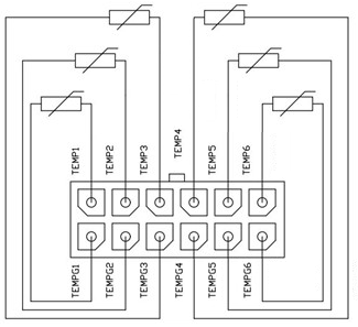
X6 – header for cells temperature sensors
Receptacle Housing: Molex 430251200. Terminals: Molex 43030

| Pin | Name | Description |
| 1 | TEMPG1 | Ground of the thermistor 1 |
| 2 | TEMPG2 | Ground of the thermistor 2 |
| 3 | TEMPG3 | Ground of the thermistor 3 |
| 4 | TEMPG4 | Ground of the thermistor 4 |
| 5 | TEMPG5 | Ground of the thermistor 5 |
| 6 | TEMPG6 | Ground of the thermistor 6 |
| 7 | TEMP1 | Signal from the thermistor 1 |
| 8 | TEMP2 | Signal from the thermistor 2 |
| 9 | TEMP3 | Signal from the thermistor 3 |
| 10 | TEMP4 | Signal from the thermistor 4 |
| 11 | TEMP5 | Signal from the thermistor 5 |
| 12 | TEMP6 | Signal from the thermistor 6 |
X7 - header for current sensor
Receptacle Housing: Molex 430250400. Terminals: Molex 43030

| Pin | Name | Description |
| 1 | +5V | Supply voltage for a current sensor 5V, max 50 mA |
| 2 | GND | Ground |
| 3 | Vcs | ADC input (current sensor output) |
| 4 | Vref | Auxiliary ADC input (current sensor reference signal) |
Х8 – header for battery cells
Receptacle Housing: Molex 430252000. Terminals: Molex 43030

| Pin | Name | Description |
| 1 | C0 | Minus of the cell stack (for measuring purposes only) |
| 2 | C2 | Cell 2 |
| 3 | C4 | Cell 4 |
| 4 | C6 | Cell 6 |
| 5 | C8 | Cell 8 |
| 6 | C10 | Cell 10 |
| 7 | C12 | Cell 12 |
| 8 | C14 | Cell 14 |
| 9 | C16 | Cell 16 |
| 10 | C18 | Cell 18 (maximum potential of the cell stack, for measuring purposes only) |
| 11 | NC | Not connected |
| 12 | C1 | Cell 1 (minimum potential with respect to C0) |
| 13 | C3 | Cell 3 |
| 14 | C5 | Cell 5 |
| 15 | C7 | Cell 7 |
| 16 | C9 | Cell 9 |
| 17 | C11 | Cell 11 |
| 18 | C13 | Cell 13 |
| 19 | C15 | Cell 15 |
| 20 | C17 | Cell 17 |
Х9 – header to power the device
Receptacle Housing: Molex 436450200. Terminals: Molex 43030

| Pin | Name | Description |
| 1 | VBAT+ | Supply voltage for BMS Mini |
| 2 | VBAT- | BMS Mini power ground |
J1 – jumper for switching CAN bus terminal resistor
To connect the terminal resistor between the CAN_H and CAN_L lines, install the jumper J1 according to the following figure:

J2 – jumper for switching RS-485 terminal resistor
To connect the terminal resistor between the RS485_A and RS485_B lines, install the jumper J1 according to the following figure:
Connection procedure
Connecting battery cells
To connect battery cells, follow figure below. Incorrect connection of the cells can damage the BMS Mini.
Begin the connection with the negative line of the battery: the “C0“ is connected to the “B-“, then the first cell (C1) is connected, then the second (С2), etc. If not all inputs of the cells are used, then the remaining inputs are connected to the cell with the most potential.

Connecting thermistors
Thermistors should be fastened to the cells, excluding short circuits to the cell terminals (for example, isolate thermistors with heat shrink).