
3.3 Управление
Настройки
Управление
Common settings
Для изменения основных настроек батареи следует выбрать раздел «Control → Common settings»:

В данном разделе:
- Cell capacity – номинальная ёмкость ячеек, А×ч;
- Cell resistance – номинальное сопротивление ячейки, Ом;
- Relax time (after charging) – время релаксации ячейки после заряда, с;
- Relax time (atfer discharging) – время релаксации ячейки после разряда, с;
- Number of cycles – количество циклов заряда-разряда, вещественное число (под одним циклом понимается разряд и заряд батареи на 80%);
- Reset parameters – команда сброса степени заряда и сопротивления ячеек.
Величины «Cell capacity» (ёмкости), «Cell resistance» (сопротивления) используются для расчёта степени заряда батареи (SOC).
Величины Relax time (времени релаксации) используются для определения состоянии батареи. Если батарея находится в состоянии релаксации, то система пересчитывает напряжение на ячейках в степень заряда (SOC).
Команда Reset parameters (сброс степени заряда и сопротивления) используется при пуско-наладочных работах при условии, что батарея находится в состоянии релаксации.
SOC estimation
Устройство BMS Mini рассчитывает степень заряда батареи (SOC) используя два алгоритма:
- по напряжению холостого хода;
- по напряжению и току.
Рекомендуется использовать алгоритм расчёта SOC по напряжению и току.
Для изменения параметров алгоритма расчёта степени заряда батареи необходимо выбрать раздел «Control → SOC estimation»:

Поддерживаются следующие алгоритмы определения степени заряда:
- Voltage – по напряжению холостого хода;
- Current and voltage (simplified) – по напряжению и току (упрощённый алгоритм, рекомендуется для ячеек LFP);
- Current and voltage (enhanced) – по напряжению и току (улучшенный алгоритм, рекомендуется для ячеек NMC).
Алгоритм "Voltage" рассчитывает SOC ячеек исходя из табличной зависимости Uocv = Uocv(SOC, t°C).
Алгоритм "Current and voltage (simplified)" работает следующим образом:
- если I = 0, батарея находится в состоянии релаксации и напряжение ячейки Uocv находится вне отрезка [Linear zone point 1; Linear zone point 2], то расчёт SOC на основе табличной зависимости Uocv = Uocv(SOC, t°C);
- в любых других случаях величина SOC пропорциональна заряду, прошедшему через батарею (интеграл тока по времени).
Алгоритм “Current and voltage (enhanced)” отличается от упрощённого алгоритма (simplified) онлайн-коррекцией эффективной ёмкости. При использовании данного алгоритма необходима точная настройка табличной зависимости Uocv = Uocv(SOC, t°C).
Для изменения параметров алгоритма расчёта финального SOC необходимо выбрать пункт «Control → SOC estimation → Final SOC»:

Поддерживаются следующие способы расчёта SOC батареи:
- Minimum SOC – SOC модульной батареи принимается равным минимальному SOC среди батарейных модулей;
- Average SOC – SOC модульной батареи принимается равным среднему арифметическому SOC батарейных модулей;
- Min-Max – SOC модульной батареи рассчитывается исходя из минимального и максимального SOC ячеек (оптимизировано для максимальной надежности батареи, рекомендуется);
- Max-Min – SOC модульной батареи рассчитывается исходя из минимального и максимального SOC ячеек (оптимизировано для максимальной ёмкости батареи);
Другие параметры:
- Scale the final SOC – флаг для масштабирования итогового SOC батареи;
- SOC corresponding to 0% - значение SOC, принимаемое за 0%.
- SOC corresponding to 100% - значение SOC, принимаемое за 100%.
- Uocv (open-circuit voltage) table – зависимость напряжения холостого хода Uocv от SOC и температуры ячейки (подбирается под конкретные ячейки; может быть установлена экспериментально);
- Linear zone – линейная зона зависимости Uocv = Uocv(SOC, t°C), внутри которой напряжение ячейки изменяется незначительно:
- Linear zone point 1 – начальная точка линейной зоны зависимости Uocv;
- Linear zone point 2 – конечная точка линейной зоны зависимости Uocv;
- Coulomb counting correction (temperature) – зависимость ёмкости батареи от температуры;
- Coulomb counting correction (cycles) – зависимость ёмкости батареи от количества циклов заряда-разряда.
SOC correction
Устройство BMS Mini может пересчитывать степень заряда батареи после длительного хранения или после длительной эксплуатации батареи в условиях частичного разряда и неполного заряда. Пересчёт выполняется на основе табличной зависимости Uocv = Uocv(SOC, t°C) (см. SOC estimation).
Для изменения параметров алгоритма корректировки степени заряда батареи необходимо выбрать раздел «Control → SOC correction»:

В данном разделе:
- Enable – флаг разрешения корректировки SOC;
- Shutdown period – время нахождения батареи в выключенном состоянии, дни. Если в момент запуска BMS определяет, что до этого батарея была отключена в течение времени Shutdown period, то BMS пересчитывает степень заряда батареи на основе зависимости Uocv = Uocv(SOC, t°C);
- Correction period – период корректировки SOC, дни. Если с момента последней корректировки прошло время, равное Correction period, то BMS пересчитывает SOC на основе зависимости Uocv = Uocv(SOC, t°C) и изменяет степень заряда батареи линейно за время SOC change time;
- SOC change time – длительность линейного изменения SOC до значения, рассчитанного на основе зависимости Uocv = Uocv(SOC, t°C), мин;
- Ignore the linear zone – флаг игнорирования линейной зоны SOC при коррекции;
- Last correction timestamp – время последней коррекции SOC.
Resistance estimation
Расчёт сопротивления ячеек выполняется двумя способами. Первый способ используется, когда батарея переходит из состояния релаксации в состояние заряда или разряда, при этом величина сопротивления ячейки
где U – напряжение ячейки, измеренное в состоянии заряда или разряда, В; Uocv – напряжение ячейки, измеренное в состоянии релаксации (до перехода в состояние заряда или разряда); Iстаб – стабилизированный ток через ячейку в состоянии заряда или разряда.
Второй способ применяется при скачкообразном изменении тока через ячейку, при этом величина сопротивления ячейки:
при условии, что
где Qmax – максимальная ёмкость ячейки, U2 – напряжение на ячейке в момент протекания через неё стабилизированного тока Iстаб2; U1 – напряжение на ячейке в момент протекания через неё стабилизированного тока Iстаб1.
Стабилизированный ток Iстаб = I, если в течение времени стабилизации мгновенное значение тока I находится в диапазоне от 0,95×I до 1,05×I.
Для изменения параметров алгоритма расчёта сопротивления ячеек необходимо выбрать раздел «Control → Resistance estimation»:

В данном разделе:
- Current stabilization time – время стабилизации тока, мс;
- Maximum calculation period – максимальное время между подсчётами сопротивления, с. Если с момента последнего определения стабилизированного тока Iстаб прошло больше времени, чем определено в данном поле, то расчёт сопротивления не выполняется.
- Maximum resistance factor – коэффициент расчёта максимального допустимого сопротивления ячейки;
- Minimum SOC – минимальная степень заряда ячейки, при которой происходит расчет сопротивления;
- Maximum SOC – максимальная степень заряда ячейки, при которой происходит расчет сопротивления;
Рассчитанное сопротивление принимается системой как допустимое (а значит обновится), если его значение находится в диапазоне от Resistance / 2 до Maximum resistance factor × Resistance, где Resistance – номинальное сопротивление ячейки (см. Common settings). Если расчётное значение сопротивления больше величины (Maximum resistance factor × Resistance), то обновлённое значение сопротивления будет равно величине (Maximum resistance factor × Resistance).
Low SOC (signal)
Для изменения параметров формирования сигнала о низком уровне заряда АКБ необходимо выбрать раздел «Control → Low SOC (signal)»:

В данном разделе:
- Enable – флаг включения формирования сигнала;
- Minimum SOC – минимальный уровень заряда, %;
- Tolerant SOC – допустимый уровень заряда, %;
- Delay before setting the signal – задержка перед формированием сигнала, с;
- Delay before clearing the signal – задержка перед снятием сигнала, с;
- Lock – флаг блокирования сигнала до перезапуска устройства.
Условия формирования сигнала «Low SOC»:
- уровень заряда батареи меньше величины «Minimum SOC» в течение времени «Delay before setting the signal».
Условия снятия сигнала:
- уровень заряда батареи больше величины «Tolerant SOC» в течение времени «Delay before clearing the signal».
High charging current (signal)
Для изменения параметров формирования сигнала о высоком токе заряда необходимо выбрать раздел «Control → High charging current (signal)»:

В данном разделе:
- Enable – флаг включения формирования сигнала;
- Maximum charging current – максимальный ток заряда, А;
- Tolerant charging current – допустимый ток заряда, А;
- Delay before setting the signal – задержка перед формированием сигнала, с;
- Delay before clearing the signal – задержка перед снятием сигнала, с;
- Lock – флаг блокирования сигнала до перезапуска устройства.
Условия формирования сигнала «High charging current»:
- измеренный ток больше величины «Maximum charging current» в течение времени «Delay before setting the signal».
Условия снятия сигнала:
- измеренный ток меньше величины «Tolerant charging current» в течение времени «Delay before clearing the signal».
Charge map
Устройство BMS Mini рассчитывает максимально допустимый ток заряда исходя из уровня заряда (SOC), температуры батареи, температуры контакторов и напряжения ячеек.
Рассчитанные величины максимально допустимого тока заряда передаются внешнему оборудованию (например, зарядному устройству) по шине CAN. Внешнее оборудование, руководствуясь полученными значениями, обеспечивает корректный режим работы батареи.
Для изменения параметров расчёта предельного тока заряда необходимо выбрать раздел «Control → Charge map»:

В данном разделе:
- Enable – флаг разрешения расчёта величины предельного тока заряда;
- Maximum charge current – максимальное значение тока заряда при нормальных условиях;
- Rate of change – скорость изменения величины предельного тока заряда (если установлен 0, то изменение тока будет происходить мгновенно), А/с;
- Option 1: Limit charge current by the battery SOC and temperature – флаг включения коррекции максимального тока заряда KCS в зависимости от максимального SOC ячеек и температуры батареи;
- Option 1: SOC x Temperature x Factor – зависимость коэффициента коррекции максимального тока заряда KCS от степени заряда батареи и температуры;
- Option 2: Limit charge current by the contactor temperature – флаг включения коррекции максимального тока заряда KCC в зависимости от температуры контактора;
- Option 2: Contactor temperature x Factor – зависимость коэффициента коррекции максимального тока заряда KCC от температуры контактора;
- Option 3: Limit charge current by the cell voltage - флаг включения коррекции максимального тока заряда KCV в зависимости от максимального напряжения холостого хода ячеек Uocv (т.е. с учетом коррекции по току и сопротивлению);
- Option 3: Cell voltage x Factor – зависимость коэффициента коррекции максимального тока заряда KCV от напряжения ячеек.
- Option 4: Limit charge current by the cell temperature - флаг включения коррекции максимального тока заряда KCT в зависимости от температуры ячеек;
- Option 4: Cell temperature x Factor – зависимость коэффициента коррекции максимального тока заряда KCT от температуры ячеек.
Величина предельного тока заряда при текущем уровне заряда и температуре батареи, температуре контактора, максимальном напряжении и температуре ячеек рассчитывается следующим образом:
Charge current limit = Maximum charge current × Kcs × Kcc × Kcv × Kct
Discharge map
Устройство BMS Mini рассчитывает максимально допустимый ток разряда исходя из уровня заряда (SOC), температуры батареи, температуры контакторов и напряжения ячеек.
Рассчитанные величины максимально допустимого тока разряда передаются внешнему оборудованию по шине CAN. Внешнее оборудование, руководствуясь полученными значениями, обеспечивает корректный режим работы батареи.
Для изменения параметров расчёта предельного тока разряда необходимо выбрать раздел «Control → Disharge map»:

В данном разделе:
- Enable – флаг разрешения расчёта величины предельного тока разряда;
- Maximum discharge current – максимальное значение тока разряда при нормальных условиях, А;
- Rate of change – скорость изменения величины предельного тока разряда (если установлен 0, то изменение тока будет происходить мгновенно), А/с;
- Option 1: Limit discharging current by the battery SOC and temperature – флаг включения коррекции максимального тока разряда KDS в зависимости от минимального SOC ячеек и температуры батареи;
- Option 1: SOC x Temperature x Factor – зависимость коэффициента коррекции максимального тока разряда KDS от степени заряда батареи и её температуры;
- Option 2: Limit discharge current by the contactor temperature – флаг включения коррекции максимального тока разряда KDC в зависимости от температуры контактора;
- Option 2: Contactor temperature x Factor – зависимость коэффициента коррекции максимального тока разряда KDC от температуры контактора;
- Option 3: Limit discharge current by the cell voltage - флаг включения коррекции максимального тока разряда KDV в зависимости от минимального напряжения холостого хода ячеек Uocv (т.е. с учетом коррекции по току и сопротивлению);
- Option 3: Cell voltage x Factor – зависимость коэффициента коррекции максимального тока разряда KDV от минимального напряжения среди ячеек.
- Option 4: Limit discharge current by the cell temperature - флаг включения коррекции максимального тока разряда KDT в зависимости от температуры ячеек;
- Option 4: Cell temperature x Factor – зависимость коэффициента коррекции максимального тока разряда KDT от температуры ячеек.
Величина предельного тока разряда при текущем уровне заряда и температуре батареи, температуре контактора, минимальном напряжении и температуре ячеек рассчитывается следующим образом:
Discharge current limit = Maximum discharge current × Kds × Kdc × Kdv × Kdt
Main contactor
Устройство BMS Mini может управлять основным контактором, который является дополнительной защитой, размыкающей силовую цепь батареи в случае залипания контакторов заряда или разряда.
Поддерживаются следующие алгоритмы работы основного контактора:
- Always on – контактор всегда замкнут;
- Automatic – контактор замыкается по внутренней команде контроллеров заряда и разряда вместе с контакторами «Precharging», «Charging» и «Discharging»;
- On demand – контактор замыкается по внешней команде.
В режиме “Always on” контактор замыкается при одновременном выполнении следующих условий:
- остальные контакторы разомкнуты;
- отсутствуют ошибки, указанные в битовых полях "Errors 1, 2 ...".
В режиме “Always on” контактор размыкается при одновременном выполнении следующих условий:
- остальные контакторы разомкнуты;
- присутствует ошибка, указанная в битовых полях "Errors 1, 2 ...".
В режиме “Automatic” контактор замыкается по внутренней команде контроллеров вместе с остальными контакторами.
В режиме “On demand” управление основным контактором осуществляется по команде «Close Main contactor».
Для изменения параметров управления основным контактором необходимо выбрать раздел «Control → Main contactor»:

В данном разделе:
- Enable – флаг включения контроллера основного контактора;
- Algorithm – алгоритм управления основным контактором:
- Always on – основной контактор всегда включен;
- Automatic – управление основным контактором выполняет BMS в соответствии с требованием заряда или разряда батареи;
- On command – управление основным контактором выполняется по сигналу «Close Main contactor»;
- Time to keep the contactor closed before closing the others – время, в течение которого другие контакторы находятся в разомкнутом состоянии после замыкания основного контактора, мс;
- Delay before opening the contactor – задержка перед открытием основного контактора, мс;
- Keep the contactor open until the device is restarted – флаг блокирования основного контактора в открытом состоянии до перезапуска устройства.
- Errors 1, 2 to open the main contactor – битовые поля для выбора ошибок, вызывающих размыкание основного контактора.
Charging status
Для изменения параметров статуса заряда необходимо выбрать раздел «Control → Charging status»:
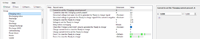
In this section:
- Current to set the "Charging current present" – уровень тока для формирования сигнала «Charging current present», А;
- Current to clear the "Charging current present" – уровень тока для снятия сигнала «Charging current present», А;
- Use actual voltage to generate the "Ready to charge" signal – флаг отключения корректировки по напряжению во время генерирования сигнала "Ready to charge";
- Use actual voltage to generate the "Ready to charge" signal if the current is negative – флаг отключения корректировки по напряжению во время генерирования сигнала "Ready to charge" только во время разряда;
- Voltage to clear the “Ready to charge” – пороговый уровень напряжения Uocv (т.е. с учетом коррекции по току и сопротивлению) на ячейке, В; если напряжение хотя бы на одной ячейке выше указанного уровня, то сигнал «Ready to charge» снимается;
- Voltage to reset the “Ready to charge” – толерантный уровень напряжения Uocv (т.е. с учетом коррекции по току и сопротивлению) на ячейке, В; если напряжение на всех ячейках ниже толерантного уровня, то сигнал «Ready to charge» устанавливается;
- Delay before recharging – величина задержки перед повторным замыканием контактора разрешения работы зарядного устройства «Allow charging», мин; для отключения работы контактора по задержке служит значение 0;
- Check the 'Charge current limit' value to generate the 'Ready to charge' – флаг включения проверки лимита тока заряда во время генерации сигнала готовности батареи к заряду;
- Charge current limit to clear the 'Ready to charge' – пороговый уровень лимита тока заряда батареи; если лимит тока выше указанного уровня, то сигнал «Ready to charge» снимается;
- Charge current limit to set the 'Ready to charge' – толерантный уровень лимита тока заряда батареи; если лимит тока ниже указанного уровня, то сигнал «Ready to charge» устанавливается;
- Errors 1, 2 to clear the "Ready to charge" – битовые поля для выбора ошибок, вызывающих снятие сигнала «Ready to charge».
Discharging status
Для изменения параметров статуса заряда необходимо выбрать раздел «Control → Discharging status»:
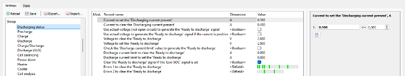
In this section:
- Current to set the "Discharging current present" – уровень тока для формирования сигнала «Discharging current present», А;
- Current to clear the "Discharging current present" – уровень тока для снятия сигнала «Discharging current present», А;
- Use actual voltage to generate the "Ready to discharge" signal – флаг отключения корректировки по напряжению во время генерирования сигнала "Ready to discharge";
- Use actual voltage to generate the "Ready to discharge" signal if the current is positive – флаг отключения корректировки по напряжению во время генерирования сигнала "Ready to discharge" только во время заряда;
- Voltage to clear the “Ready to discharge” signal – пороговый уровень напряжения Uocv (т.е. с учетом коррекции по току и сопротивлению) на ячейке, В; если напряжение хотя бы на одной ячейке ниже указанного уровня, то сигнал «Ready to discharge» снимается;
- Voltage to reset the “Ready to discharge” signal – толерантный уровень напряжения Uocv (т.е. с учетом коррекции по току и сопротивлению) на ячейке, В; если напряжение на всех ячейках ниже толерантного уровня, то сигнал «Ready to discharge» устанавливается.
- Check the 'Dischharge current limit' value to generate the 'Ready to discharge' – флаг включения проверки лимита тока разряда во время генерации сигнала готовности батареи к разряду;
- Discharge current limit to clear the 'Ready to discharge' – пороговый уровень лимита тока разряда батареи; если лимит тока выше указанного уровня, то сигнал «Ready to discharge» снимается;
- Discharge current limit to set the 'Ready to discharge' – толерантный уровень лимита тока разряда батареи; если лимит тока ниже указанного уровня, то сигнал «Ready to discharge» устанавливается;
- Clear the 'Ready to discharge' signal if the 'Low SOC' signal is set – флаг снятия сигнала "Ready to charge" при наличии сигнала "Low SOC";
- Errors 1, 2 to clear the "Ready to discharge" – битовые поля для выбора ошибок, вызывающих снятие сигнала «Ready to discharge».
Precharge
Устройство BMS Main 3 может управлять контактором предзаряда. Контактор предзаряда используется для заряда промежуточной ёмкости низким током и обычно располагается с ограничивающим резистором параллельно зарядному или разрядному контактору.
BMS Main 3 обнаруживает ошибки во время предзаряда через отслеживание тока и разницы напряжения до и после контакторов. Также BMS измеряет рассеиваемую на резисторе предзаряда мощность и формирует ошибку, если мощность превышает установленный лимит.
TBA
Для изменения параметров алгоритма управления предразрядом необходимо выбрать раздел «Control → Precharge»:

В данном разделе:
- Precharge current threshold to finish precharging – ток батареи, при котором BMS считает, что предзаряд завершен, А;
- Keep the precharging relay closed until precharge is finished – флаг ожидания завершения процесса предзаряда независимо от Precharging time;
- Number of precharging attempts – максимальное количество попыток предзаряда перед формированием ошибки "Precharge error";
- Delay before current measurement – задержка перед первым измерением тока после включения BMS, мс;
- Precharge time – длительность включения контактора предзаряда перед замыканием контактора разряда, мс;
- Relaxation between attempts – задержка между повторными попытками предзаряда, мс;
- Check the power dissipated in the preacharge resistor - флаг проверки рассеиваемой мощности на резисторе предзаряда;
- Precharge resistor resistance – сопротивление резистора предзаряда, Ом;
- Maximum allowable power dissipated in the resistor – максимальная разрешенная мощность, рассеиваемая на резисторе предзаряда, Вт;
- Delay before setting the "Precharge error" when checking power – задержка перед формированием ошибки «Precharge error» во время проверки рассеиваемой мощности на резисторе, мс;
- Delay before clearing the "Precharge error" – задержка перед снятием ошибки, с;
- Lock the "Precharge error" – флаг блокирования ошибки до перезапуска устройства.
Ошибка “Precharge error” формируется, если происходит хотя бы одно из слежущих событий:
- ток предзаряда не снизился ниже порогового значения за время the "Precharge time" после "Number of precharging attempts" попыток;
- мощность, рассеиваемая на резисторе предзаряда, выше установленного предела в течении времени “Delay before setting the 'Precharge error' when checking power”.
Поведение контакторов во время ошибки “Precharge error” задается в настройках соответствующего контактора!
Charge
Для заряда батареи служат два контактора: контактор заряда и контактор разрешения работы зарядного устройства. С помощью последнего контактора BMS оповещает ЗУ о необходимости включения.
Устройство поддерживает три алгоритма управления зарядом:
- Always on – заряд всегда разрешён;
- On charger connected – заряд разрешён при наличии сигнала подключения зарядного устройства “Charger connected”;
- On charge request – заряд разрешен при наличии сигнала запроса заряда “Charge request”.
При выборе алгоритма «Always on» контактор заряда и контактор разрешения работы зарядного устройства "Allow charging" всегда замкнуты. При появлении хотя бы одной из ошибок, указанных в битовых полях "Errors 1, 2 ...", или одного из сигналов:
- Service reset;
- Power down request;
- Inhibit charging,
оба контактора размыкаются.
При выборе алгоритма «On charger connected» управление контакторами выполняется следующим образом:
- если есть сигнал «Charger connected» и отсутствуют сигналы и ошибки из списка выше, то через время задержки Tвкл. замыкаются контактор заряда «Charging» и контактор разрешения работы зарядного устройства «Allow charging»;
- если сигнал «Charger connected» снимается, то размыкается контактор разрешения работы зарядного устройства «Allow charging» и через время задержки Tоткл. размыкается контактор заряда;
- если в процессе заряда напряжение на ячейке превысит заданный уровень, то размыкается контактор разрешения работы зарядного устройства «Allow charging»; при этом контактор заряда «Charging» остаётся замкнутым;
- если появляются сигналы или ошибки из списка выше, то контактор заряда «Charging» и контактор разрешения работы зарядного устройства «Allow charging» размыкаются.
При выборе алгоритма «On charge request» управление контактором выполняется следующим образом:
- если есть сигнал о запросе заряда «Charge request» и отсутствуют сигналы и ошибки из списка выше, то через время задержки Tвкл. замыкаются контактор заряда «Charging» и контактор разрешения работы зарядного устройства «Allow charging»;
- если сигнал «Charge request» снимается, то размыкается контактор разрешения работы зарядного устройства «Allow charging» и через время задержки Tоткл. размыкается контактор заряда «Charging»;
- если в процессе заряда напряжение на ячейке превысит уровень «Ready to charge», то размыкается контактор разрешения работы зарядного устройства «Allow charging»; при этом контактор заряда «Charging» остаётся замкнутым;
- если появляются сигналы или ошибки из списка выше, то контактор заряда «Charging» и контактор разрешения работы зарядного устройства «Allow charging» размыкаются.
Для изменения параметров алгоритма управления зарядом батареи необходимо выбрать раздел «Control → Charge»:

В данном разделе:
- Enable – флаг включения контроллера заряда батареи;
- Algorithm – алгоритм управления зарядом:
- Always on – заряд всегда разрешён;
- On charger connected – заряд разрешён при наличии сигнала «Charger connected»;
- On charge request– заряд разрешён при наличии сигнала «Charge request»;
- Allow charging only when the "Ready to charge" signal is set – флаг, разрешающий заряд только если установлен сигнал "Ready to charge";
- Delay before starting charging – время задержки Tвкл. перед включением заряда батареи, мс;
- Delay before stopping charging – время задержки Tоткл. перед отключением заряда батареи, мс;
- Control the precharging contactor – флаг активации управления контактором предзаряда перед замыканием контактора заряда (см. Precharge);
- Errors 1, 2 to open the charging contactor – битовые поля для выбора ошибок, вызывающих размыкание контактора заряда;
- Use custom delays before stopping charging (on errors) – флаг включения ручной настройки времени задержки Tоткл в зависимости от типа ошибки;
- Custom delay: <error> - время задержки соответствующий ошибки, мс;
- Switch off the charging contactor on errors without a delay – флаг, при установке которого контактор заряда будет размыкаться без задержки, если обнаружены ошибки. В обратном случае при обнаружении ошибок контактор заряда размыкается всегда с задержкой «Delay before stopping charging».
Discharge
Для подключения нагрузки к батарее служит контактор разряда.
Устройство поддерживает три алгоритма управления разрядом батареи:
- Always on – нагрузка всегда подключена ;
- On charger disconnected – подключение нагрузки при отсутствии сигнала о подключении зарядного устройства “Charger connected”;
- On discharge request – подключение нагрузки при наличии сигнала запроса разряда “Discharge request”.
При выборе алгоритма «Always on» контактор разряда всегда замкнут. При появлении хотя бы одной из ошибок, указанных в битовых полях "Errors 1, 2 ...", или одного из сигналов:
- Service reset
- Power down request
- Inhibit discharging
контактор разряда размыкается.
При выборе алгоритма «On charger disconnected» управление контактором разряда выполняется следующим образом:
- если отсутствует сигнал «Charger connected» контактор заряда разомкнут и отсутствуют сигналы и ошибки из списка выше, то через время задержки Tвкл. замыкается контактор разряда «Discharging»;
- если появляется сигнал «Charger connected» или появляются сигналы или ошибки из списка выше, то через время задержки Tоткл. размыкается контактор разряда «Discharging».
При выборе алгоритма «On discharge request» управление контактором выполняется следующим образом:
- если присутствует сигнал «Discharge request» и отсутствуют сигналы и ошибки из списка выше, то через время задержки Tвкл. замыкается контактор разряда «Discharging»;
- если сигнал «Discharge request» пропадает или появляются сигналы или ошибки из списка выше, то через время задержки Tоткл. размыкается контактор разряда «Discharging».
Для изменения параметров алгоритма управления разрядом батареи необходимо выбрать раздел «Control → Discharge»:

В данном разделе:
- Enable – флаг включения контроллера разряда батареи;
- Algorithm – алгоритм управления разрядом:
- Always on – нагрузка всегда подключена;
- On charger disconnected – разряд разрешён при снятии сигнала «Charger connected»;
- On discharge request - разряд разрешён при наличии сигнала «Discharge request»;
- Allow charging only when the "Ready to discharge" signal is set – флаг, разрешающий разряд только если установлен сигнал "Ready to discharge";
- Delay before starting discharging – время задержки Tвкл. перед включением разряда батареи, мс;
- Delay before stopping discharging – время задержки Tоткл. перед отключением разряда батареи, мс;
- Control the precharging contactor – флаг активации управления контактором предзаряда перед замыканием контактора разряда (см. Precharge);
- Errors 1, 2 to open the discharging contactor – битовые поля для выбора ошибок, вызывающих размыкание контактора разряда;
- Use custom delays before stopping discharging (on errors) – флаг включения ручной настройки времени задержки Tоткл в зависимости от типа ошибки;
- Custom delay: <error> – время задержки соответствующей ошибки, мс;
- Switch off the discharging contactor on errors without a delay – флаг, при установке которого контактор разряда будет размыкаться без задержки, если обнаружены ошибки. В обратном случае при обнаружении ошибок контактор разряда размыкается всегда с задержкой Delay before stopping discharging.
Charge/Discharge
Устройство BMS Mini может управлять контактором заряда/разряда, который сочетает в себе алгоритмы работы контактора заряда и разряда. Контактор работает по алгоритму контактора заряда при наличии сигнала «Charge request» или «Charger connected», иначе – по алгоритму контактора разряда.
Контактор заряда/разряда имеет три алгоритма управления:
- Dependent (on Charging and Discharging signals) – контактор заряда/разряда зависит от алгоритмов управления зарядом и разрядом. Контактор работает по алгоритму контактора заряда при наличии сигнала «Charge request» или «Charger connected», иначе – по алгоритму контактора разряда;
- Independent (Always) – контактор заряда/разряда замкнут всегда при отсутствии ошибок;
- Independent (on Charge request or Discharge request) – контактор заряда/разряда работает по собственному алгоритму и замыкается при появлении запросов на заряд или разряд — «Charge request» или «Discharge request».
TBA
Для изменения параметров алгоритма управления контактором заряда/разряда следует необходимо выбрать раздел «Control → Charge/Discharge»:

В данном разделе:
- Enable – флаг включения контроллера контактора заряда/разряда.
- Algorithm – алгоритм работы контактора "Charge/Discharge":
- Dependent (on Charging and Discharging signals) – контактор заряда/разряда зависит от алгоритмов управления зарядом и разрядом;
- Independent (Always) – контактор заряда/разряда замкнут всегда при отсутствии ошибок;
- Independent (on Charge request or Discharge request) – контактор заряда/разряда работает по собственному алгоритму и замыкается при появлении запросов на заряд или разряд — «Charge request» или «Discharge request».
- Delay before starting discharging – время задержки Tвкл. перед включением контактора заряда/разряда, мс;
- Delay before stopping discharging – время задержки Tоткл. перед отключением контактора заряда/разряда, мс;
- Control the precharging contactor – флаг активации управления контактором предзаряда перед замыканием контактора заряда/разряда;
- Emulate the "Charging" and "Discharging" signals – флаг эмуляции сигналов "Charging" and "Discharging" во время замыкания контактора заряда/разряда;
- Errors 1, 2 to prevent CHARGING through charging/discharging contactor, Errors 1, 2 to prevent DISCHARGING through charging/discharging contactor – битовые поля для выбора ошибок, вызывающих размыкание контактора заряда/разряда. Эти битовые поля комбинированы побитовым ИЛИ и предназначены для разделения настроек отдельно для заряда и разряда;
- Errors 1, 2 which affect the contactor only if battery CHARGING is detected – битовые поля для выбора ошибок, вызывающих размыкание контактора заряда/разряда только во время заряда. Это битовое поле объединено с полем "Errors 1, 2 to prevent CHARGING through charging/discharging contactor" побитовым И;
- Errors 1, 2 which affect the contactor only if battery DISCHARGING is detected – битовые поля для выбора ошибок, вызывающих размыкание контактора заряда/разряда только во время разряда. Это битовое поле объединено с полем "Errors 1, 2 to prevent DISCHARGING through charging/discharging contactor" побитовым И;
- Switch off the charging/discharging contactor on errors without a delay – флаг, при установке которого контактор заряда/разряда будет размыкаться без задержки, если обнаружены ошибки. В обратном случае при обнаружении ошибок контактор заряда/разряда размыкается всегда с задержкой Delay before stopping discharging.
Discharge (AUX)
Устройство BMS Mini может управлять питанием внешнего оборудования с помощью дополнительного (AUX) контактора разряда. Примером внешнего оборудования может быть инвертор, который преобразует постоянный ток в переменный для питания сервисного ноутбука и других устройств.
Цепь питания внешнего оборудования с помощью дополнительного (AUX) контактора разряда является независимой от цепи нагрузки батареи. Замыкание и размыкание дополнительного (AUX) контактора разряда выполняется по своей программе.
Если функция питания внешнего оборудования разрешена, то дополнительный (AUX) контактор разряда замыкается. Размыкание данного контактора происходит по трём независимым друг от друга условиям:
- батарея имеет низкий уровень заряда (SOC);
- напряжение батареи находится вне заданного диапазона;
- обнаружены ошибки в работе батарейной системы.
Для изменения параметров алгоритма управления питанием внешнего оборудования необходимо выбрать раздел «Control → Discharge (AUX)»:

В данном разделе:
- Enable – флаг включения контроллера питания внешнего оборудования;
- Switch off the discharging (AUX) contactor if the SOC is too low – включение функции размыкания дополнительного (AUX) контактора разряда при снижении SOC ниже значения Minimum SOC;
- Minimum SOC – минимальное значение SOC, при достижении которого происходит размыкание дополнительного (AUX) контактора разряда, %;
- Tolerant SOC – допустимое значение SOC, при достижении которого происходит повторное замыкание дополнительного (AUX) контактора разряда, %;
- Switch off the discharging (AUX) contactor if the cell voltage is out of the range – включение функции размыкания дополнительного (AUX) контактора разряда при напряжении ячеек вне указанных пределов;
- Minimum cell voltage – минимальное значение напряжения ячейки, при достижении которого происходит размыкание дополнительного (AUX) контактора разряда, В;
- Maximum cell voltage – максимальное значение напряжения ячейки, при достижении которого происходит размыкание дополнительного (AUX) контактора разряда, В;
- Switch off the discharging (AUX) contactor if the battery voltage is out of the range – включение функции размыкания дополнительного (AUX) контактора разряда при напряжении батареивне указанных пределов;
- Minimum battery voltage – минимальное значение напряжения батареи, при достижении которого происходит размыкание дополнительного (AUX) контактора разряда, В;
- Maximum battery voltage – максимальное значение напряжения батареи, при достижении которого происходит размыкание дополнительного (AUX) контактора разряда, В;
- Errors 1, 2 to open the auxiliary discharging contactor – битовые поля для выбора ошибок, вызывающих размыкание внешнего контактора разряда.
Cell balancing
Балансировка в пределах всей батареи приводит напряжение всех ячеек к напряжению ячейки, имеющей наименьший заряд.
Поддерживаются следующие правила балансировки:
- при заряде батареи;
- при заряде батареи или в случае, когда батарея находится в состоянии релаксации;
- независимо от состояния батареи.
К ячейке подключается балансировочный резистор если одновременно выполняются следующие условия:
- напряжение на ячейке выше напряжения запуска балансировки;
- разница между напряжением на ячейке и минимальным напряжением среди ячеек батареи больше порога запуска балансировки;
От ячейки отключается балансировочный резистор если выполняется любое из условий:
- напряжение на ячейке меньше напряжения запуска балансировки;
- разница между напряжением на ячейке и минимальным напряжением среди ячеек батареи меньше порога останова балансировки;
В BMS Mini имеется возможность запустить балансировку ячеек по внешнему сигналу «Balancing request». Балансировка будет запущена для тех ячеек, напряжение которых больше напряжения запуска балансировки и разница между их напряжением и минимальным напряжением среди ячеек батареи больше порога останова балансировки.
BMS Mini имеет возможность принудительной балансировки ячейки, если её напряжение выше установленного значения.
Для изменения параметров балансировки ячеек необходимо выбрать раздел «Control → Cell balancing»:

В данном разделе:
- Enable – флаг разрешения балансировки;
- Balancing rule – правило балансировки:
- Balance on charge – при заряде батареи (состояние Charging ON) и после отключения заряда (Charging OFF);
- Balance on charge or relaxed – при заряде батареи (состояние Charging ON или Charging OFF) и в состоянии релаксации батареи (Relaxed (after charging) или Relaxed (after discharging));
- Balance always – всегда (независимо от состояния батареи);
- Balancing condition – условие балансировки:
- Automatic – балансировка будет производсится автоматически, когда соблюдены все условия балансировки;
- On balancing request – балансировка производится только при поступлении сигнала "Balancing request". В это случае балансировки начнется независимо от значения "Voltage deviation to start balancing";
- Minimum cell voltage to start balancing – напряжение запуска балансировки, В;
- Voltage deviation to start balancing – порог запуска балансировки, В;
- Voltage deviation to stop balancing – порог останова балансировки, В;
- Voltage for forced balancing – напряжение ячейки, при котором к ней принудительно будет подключен балансировочный резистор, В;
- Maximum allowable temperature of the board – максимально разрешенная температура BMS Mini, ºC;
- Command to discharge all cells – флаг принудительной балансировки всех ячеек батареи.
Power down
Устройство BMS Mini может выполнять отключение батарейной системы при низком напряжении или длительной неактивности батареи.
Отключение питания при низком напряжении осуществляется при выполнении следующих условий:
- напряжение батареи ниже минимального значения;
- сигнал «подключено ЗУ» отсутствует в течение 60 секунд.
Отключение питания при длительной неактивности осуществляется в том случае, если батарея находится в состоянии Charging OFF, Discharging OFF, Relaxed (after charging) или Relaxed (after discharging) в течение заданного времени.
Для изменения параметров управления отключением питания необходимо выбрать раздел «Control → Power down»:

В данном разделе:
- Minimum voltage to power down – минимальное напряжение батареи, при котором отключается питание батарейной системы, В;
- Idle time to power down – время простоя батареи, по истечение которого отключается питание батарейной системы, мин;
- Wait the "Power up/down request" is cleared (on startup) – флаг включения ожидания сброса сигнала на включение/отключение питания BMS при запуске устройства;
- Delay before setting the internal power down signal – задержка перед отключением питания устройства при поступлении команды «Power down request», мс.
Heater
Для изменения параметров алгоритма управления нагревателем необходимо выбрать раздел «Control → Heater»:
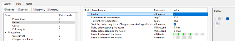
В данном разделе:
- Enable – флаг включения контроллера нагрева;
- Minimum cell temperature – минимальная температура ячеек, °C;
- Tolerant cell temperature – допустимая температура ячеек, °C;
- Start the heater only if the 'Charger connected' signal is set – флаг режима запуска нагревателя только при наличии сигнала "Charger connected";
- Delay before starting the heater – задержка перед запуском нагревателя, мс;
- Delay before stopping the heater – задержка перед остановом нагревателя, мс;
- Errors 1, 2 to turn off the heater – битовые поля для выбора ошибок, выключающих нагреватель.
Условия включения нагревателя:
- минимальная температура среди всех ячеек батареи меньше величины Minimum cell temperature в течение времени Delay before starting the heater.
Условия отключения нагревателя:
- минимальная температура среди всех ячеек батареи больше величины Tolerant cell temperature в течение времени Delay before stopping the heater.
Cooler
Для изменения параметров алгоритма управления охладителем необходимо выбрать раздел «Control → Cooler»:

В данном разделе:
- Enable – флаг включения контроллера охлаждения;
- Maximum cell temperature – максимальная температура ячеек, °C;
- Tolerant cell temperature – допустимая температура ячеек, °C;
- Delay before starting the cooler – задержка перед запуском охладителя, мс;
- Delay before stopping the cooler – задержка перед остановом охладителя, мс;
- Errors 1, 2 to turn off the heater – битовые поля для выбора ошибок, выключающих охладитель.
Условия включения охладителя:
- максимальная температура среди всех ячеек батареи больше величины Maximum cell temperature в течение времени Delay before starting the cooler.
Условия снятия сигнала:
- максимальная температура среди всех ячеек батареи меньше величины Tolerant cell temperature в течение времени Delay before stoppong the cooler.
Cell analysis
Разрядная характеристики батареи – зависимость Uocv = Uocv(DOD) – используется для определения табличной зависимости Uocv = Uocv(SOC, t°C), которая необходима для расчёта степени заряда батареи.
Устройство BMS Mini имеет возможность автоматически определить разрядную характеристику батареи.
Перед запуском процесса определения разрядной характеристики необходимо подготовить BMS:
- Полностью зарядить батарею.
- Подключить к контактору разряда резистивную нагрузку, которая обеспечит ток разряда 0,5C (где C – ёмкость ячейки).
Для настройки параметров определения разрядной характеристики батареи необходимо выбрать раздел «Control → Cell analysis»:

В данном разделе:
- Enable – флаг запуска алгоритма;
- Discharge step – шаг разряда, А×ч;
- Delta voltage – величина падения напряжения на анализируемой ячейке, В;
- Cell index – позиция анализируемой ячейки;
- Analyse the most discharged cell – флаг, при установке которого будут сохранятся параметры наименее заряженной ячейки (в этом случае значение Cell index игнорируется).
Величину Discharge step рекомендуется устанавливать равной
Discharge step= С/21,
где С – ёмкость ячейки.
Разрядная характеристика будет построена для заданной ячейки (её положение определяется полем Cell index).
Алгоритм определения разрядной характеристики батареи будет запущен если установить флаг Enable. С этого момента управление контактором разряда осуществляет данный алгоритм.
Шаги алгоритма:
- Разряд DOD = 0.
- Размыкание контактора разряда.
- Ожидание релаксации батареи.
- Измерение Uocv = U.
- Сохранение точки разрядной характеристики (Q, Uocv).
- Замыкание контактора разряда. DOD1 = DOD + Discharge step, U1 = U
- Если DOD = DOD1 или U < U1 - Delta voltage, то переход к п.2.
- Если обнаружена ошибка «низкое напряжение», то конец алгоритма.
В ходе работы алгоритма на SD-карте будет создан файл с именем "CELLANALYSIS.TXT" в формате CSV (разделитель – символ табуляции).
Структура файла:
| Time | DOD | Cell | OCV | Resistance |
| 10.11.2017 12:28:34 | 0.0 | 1 | 4.180 | 0.080000 |
| ... | ... | … | ... | ... |
Названия параметров:
- Time – дата и время;
- DOD – глубина разряда, А×ч;
- Cell – позиция ячейки, для которой приводятся данные OCV и Resistance;
- OCV – напряжение Uocv ячейки, В;
- Resistance – сопротивление ячейки, Ом.