2. Установка и подключение
Installation and connection
Установка
Место крепления устройства должно быть защищено от попадания механических объектов (пыли, грязи, крупных объектов) и воды. BMS Mini S рекомендуется располагать вблизи ячеек, которые контролирует устройство, но вдали от цепей высокого тока для уменьшения воздействия электромагнитных помех на измерительные цепи.
Место крепления должно предполагать удобный доступ к устройству для подключения других элементов батарейной системы: датчика тока, контакторов, панелей индикации.
Устройство BMS Mini S имеет радиатор для рассеивания тепла, выделяющегося при балансировке ячеек. При использовании в закрытых корпусах необходимо обеспечить съем тепла с радиатора, в противном случае это может привести к повреждению устройства.
Габаритные и установочные размеры BMS Mini S приведены ниже.


| Параметр | Значение |
| Габаритные размеры (длина × ширина × высота), мм | 124,5 × 117 × 16 |
| Установочные размеры (длина × ширина), мм | 115 × 111 |
| Установочные отверстия | M3 |
Разъёмы
There are names and locations of the BMS Mini S headers on figure below.

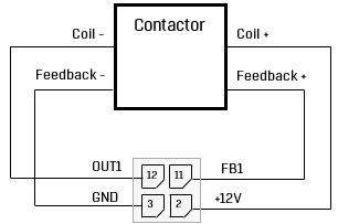
X1 – разъём для подключения контакторов.

| Контакт | Название | Назначение |
| 1 | - | - |
| 2 | +12V | Напряжение источника питания 12В |
| 3 | GND | Земля |
| 4 | +12V | Напряжение источника питания 12В |
| 5 | GND | Земля |
| 6 | +12V | Напряжение источника питания 12В |
| 7 | GND | Земля |
| 8 | +12V | Напряжение источника питания 12В |
| 9 | GND | Земля |
| 10 | - | - |
| 11 | FB1 | Сигнал обратной связи контактора 1 |
| 12 | OUT1 | Выход на контактор 1 (ключ нижнего уровня), 60В, не более 5А |
| 13 | FB2 | Сигнал обратной связи контактора 2 |
| 14 | OUT2 | Выход на контактор 2 (ключ нижнего уровня), 60В, не более 5А |
| 15 | FB3 | Сигнал обратной связи контактора 3 |
| 16 | OUT3 | Выход на контактор 3 (ключ нижнего уровня), 60В, не более 5А |
| 17 | FB4 | Сигнал обратной связи контактора 4 |
| 18 | OUT4 | Выход на контактор 4 (ключ нижнего уровня), 60В, не более 5А |
X2 – mini-USB connector.
Mini0USB connector is used for configuring the BMS via ElectricDeviceMonito
X3 – header for discrete inputs and outputs signals.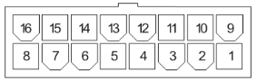
| Pin | Name | Description |
| 1 | DIN1 | Discrete input 1 “dry contact” (+5V) |
| 2 | DIN2 | Discrete input 2 “dry contact” (+5V) |
| 3 | DIN3 | Discrete input 3 “dry contact” (+5V) |
| 4 | DIN4 | Discrete input 4 “dry contact” (+5V) |
| 5 | DOUT1 | Discrete output 1 (+5V, 20mA) |
| 6 | DOUT2 | Discrete output 2 (+5V, 20mA) |
| 7 | DOUT3 | Discrete output 3 (+5V, 20mA) |
| 8 | DOUT4 | Discrete output 4 (+5V, 20mA) |
| 9 | GND | Discrete input 1 “dry contact” (ground) |
| 10 | GND | Discrete input 2 “dry contact” (ground) |
| 11 | GND | Discrete input 3 “dry contact” (ground) |
| 12 | GND | Discrete input 4 “dry contact” (ground) |
| 13 | GND | Discrete output 1 (ground) |
| 14 | GND | Discrete output 2 (ground) |
| 15 | GND | Discrete output 3 (ground) |
| 16 | GND | Discrete output 4 (ground) |
Х4 – header for САN and RS485 interfaces.

| Pin | Name | Description |
| 1 | RS485_B | RS485 line B |
| 2 | +5V | Isolated supply voltage 5V, max 400mA |
| 3 | CAN_L | CAN-L line of the CAN bus |
| 4 | RS485_A | RS485 line A |
| 5 | GND | Isolated ground |
| 6 | CAN_H | CAN-H line of the CAN bus |
Х5 – header for ON/OFF button.
| Pin | Name | Description |
| 1 | BTN | Signal to turn on/off the BMS (“dry contact”, +3.3V) |
| 2 | GND | Signal to turn on/off the BMS (“dry contact”, ground) |
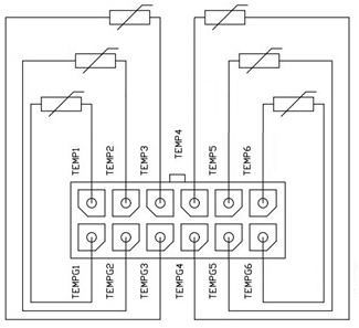
X6 – header for cells temperature sensors.

| Pin | Name | Description |
| 1 | TEMPG1 | Ground of the thermistor 1 |
| 2 | TEMPG2 | Ground of the thermistor 2 |
| 3 | TEMPG3 | Ground of the thermistor 3 |
| 4 | TEMPG4 | Ground of the thermistor 4 |
| 5 | TEMPG5 | Ground of the thermistor 5 |
| 6 | TEMPG6 | Ground of the thermistor 6 |
| 7 | TEMP1 | Signal from the thermistor 1 |
| 8 | TEMP2 | Signal from the thermistor 2 |
| 9 | TEMP3 | Signal from the thermistor 3 |
| 10 | TEMP4 | Signal from the thermistor 4 |
| 11 | TEMP5 | Signal from the thermistor 5 |
| 12 | TEMP6 | Signal from the thermistor 6 |
X7 - header for current sensor.
| Pin | Name | Description |
| 1 | +5V | Supply voltage for a current sensor 5V, max 50 mA |
| 2 | GND | Ground |
| 3 | Vcs | ADC input (current sensor output) |
| 4 | Vref | Auxiliary ADC input (current sensor reference signal) |
Х8 – header for battery cells

| Pin | Name | Description |
| 1 | C0 | Minus of the cell stack (for measuring purposes only) |
| 2 | C2 | Cell 2 |
| 3 | C4 | Cell 4 |
| 4 | C6 | Cell 6 |
| 5 | C8 | Cell 8 |
| 6 | C10 | Cell 10 |
| 7 | C12 | Cell 12 (maximum potential of the cell stack, for measuring purposes only) |
| 8 | NC | Not connected |
| 9 | C1 | Cell 1 (minimum potential with respect to C0) |
| 10 | C3 | Cell 3 |
| 11 | C5 | Cell 5 |
| 12 | C7 | Cell 7 |
| 13 | C9 | Cell 9 |
| 14 | C11 | Cell 11 |
Х9 – header to power the device

| Pin | Name | Description |
| 1 | VBAT+ | Supply voltage for BMS Mini S |
| 2 | VBAT- | BMS Mini S power ground |
J1 – jumper for switching CAN bus terminal resistor
To connect the terminal resistor between the CAN_H and CAN_L lines, install the jumper J1 according to the following figure:

J2 – jumper for switching RS-485 terminal resistor
To connect the terminal resistor between the RS485_A and RS485_B lines, install the jumper J1 according to the following figure:
Connection procedure
Connecting battery cells
To connect battery cells, follow figure below. Incorrect connection of the cells can damage the BMS Mini.
Begin the connection with the negative line of the battery: the “C0“ is connected to the “B-“, then the first cell (C1) is connected, then the second (С2), etc. If not all inputs of the cells are used, then the remaining inputs are connected to the cell with the most potential.

Connecting thermistors
Thermistors should be fastened to the cells, excluding short circuits to the cell terminals (for example, isolate thermistors with heat shrink).