Installation and connection
Installation
The mounting area of the BMS Main X 2.x must be protected from mechanical particles (dust, dirt, large objects) and water.
The installation site must provide convenient access for subsequent connection to the device’s headers for connecting other system elements: contactors, temperature sensors, etc.
Overall and mounting dimensions of the BMS Main X 2.x are shown in Figures 6 and 7.


Parameter | Value |
Overall dimensions (length × width × height), mm | 105 × 115 × 15 |
| Mounting dimensions (length × width), mm | 99 × 109 |
| Mounting holes | M3 |
Connection
Headers
There are names and locations of the BMS Main X headers in figure below.

Х1 – header for power supply

| Pin | Name | Description |
| 1 | V+ | Supply voltage 18÷36V |
| 2 | GND | Ground |
X2 – header for USB
X3 – header for CAN (INT) interface

| Pin | Name | Description |
| 1 | СAN_INT_H | CAN-H line of the internal CAN bus (communication with battery modules) |
| 2 | CAN_INT_L | CAN-L line of the internal CAN bus (communication with battery modules) |
| 3 | CAN_INT_5V | Isolated 5V power supply for internal devices, max 200 mA |
| 4 | CAN_INT_GND | Isolated ground |
Х4 – header for RS-485 interface
| Pin | Name | Description |
| 1 | RS485_A | A line of the external RS-485 bus |
| 2 | RS485_B | B line of the external RS-485 bus |
| 3 | - | - |
| 4 | RS485_GND | Isolated ground |
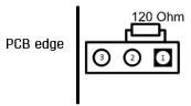
J1 – jumper for switching RS-485 terminal resistor
To connect the terminal resistor between the RS485_A and RS485_B lines, install the jumper J1 according to the following figure: