
Headers
The BMS Main 2.1 headers are shown in figure below.
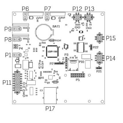
The BMS Main 2.1 headers
P1 – header for power supply

| Pin | Name | Description |
| 1 | GND | Ground |
| 2 | V+ | Supply voltage 9-30V |
P15 – header for BMS Logic

| Pin | Name | Description |
| 1 | RS485_A | RS-485 line A for communication with BMS Logic |
| 2 | RS485_B | RS-485 line B for communication with BMS Logic |
| 3 | +5V | Supply voltage for BMS Logic |
| 4 | GND | Ground |
P12 – header for current sensor

| Pin | Name | Description |
| 1 | +5V | Supply voltage for the current sensor 5V, max 50 mA |
| 2 | GND | Ground |
| 3 | Vcs | ADC input (current sensor output) |
| 4 | Vref | ADC input (current sensor reference signal) |
P13 – header for humidity sensor

| Pin | Name | Description |
| 1 | +5V | Supply voltage 5 V, max 50 mA |
| 2 | GND | Ground |
| 3 | Vhs | ADC input (humidity sensor output) |
| 4 | Vts | ADC input (temperature sensor output) |
P8 – header of relay 1

By default, relay 1 is used to control the discharging contactor.
| Pin | Name | Description |
| 1 | V+ | Switching voltage (up to 55V, max 2A) |
| 2 | NO | Normally open contact |
P9 – header of relay 2

By default, relay 2 is used to output the “Allow charging” signal.
| Pin | Name | Description |
| 1 | V+ | Switching voltage (up to 55V, max 2A) |
| 2 | NO | Normally open contact |
P6 – header of relay 3
By default, relay 3 is used to control the charging contactor.
| Pin | Name | Description |
| 1 | V+ | Switching voltage (up to 55V, max 8A) |
| 2 | NO | Normally open contact |
P7 – header of relay 4
By default, relay 4 is used to control the heater.
| Pin | Name | Description |
| 1 | V+ | Switching voltage (up to 55V, max 8A) |
| 2 | NO | Normally open contact |
P14 – header for CAN and RS-485 interfaces

| Pin | Name | Description |
| 1 | EXT_RS485_A | RS-485 line A for communication with external equipment |
| 2 | CAN_H | CAN H line for communication with external equipment |
| 3 | +5V_CAN | Supply voltage 5V for external devices, max 200 mA |
| 4 | EXT_RS485_B | RS-485 line B for communication with external equipment |
| 5 | CAN_L | CAN L line for communication with external equipment |
| 6 | GND_CAN | Ground |
P21 – CAN termination resistor jumper

To connect the termination resistor between the lines CAN_H and CAN_L, install a jumper, according to the P21 pinout:
| Pin | Name | Description |
| 1-2 | 120 Ohm | Termination resistor 120 Ohm is connected |
| 2-3 | - | Termination resistor 120 Ohm is not connected |
P22 - RS-485 termination resistor jumper

To connect the termination resistor between the EXT_RS485_A and EXT_RS485_B lines, install a jumper according to the P22 pinout:
| Pin | Name | Description |
| 1-2 | 120 Ohm | Terminating resistor 120 Ohm is connected |
| 2-3 | - | Terminating resistor 120 Ohm is not connected |
P11 – header for discrete inputs/outputs

| Pin | Name | Description |
| 16 | IN_1 | Discrete input #1 “dry contact” (+5V) |
| 8 | GND_1 | Discrete input #1 “dry contact” (ground) |
| 15 | IN_2 | Discrete input #2 “dry contact” (+5V) |
| 7 | GND_2 | Discrete input #2 “dry contact” (ground) |
| 14 | IN_3 | Discrete input #3 “dry contact” (+5V) |
| 6 | GND_3 | Discrete input #3 “dry contact” (ground) |
| 13 | IN_4 | Discrete input #4 “dry contact” (+5V) |
| 5 | GND_4 | Discrete input #4 “dry contact” (ground) |
| 12 | OUT_4 | Discrete output #4 (+5V, 20mA) |
| 4 | GND_OUT_4 | Discrete output #4 (ground) |
| 11 | OUT_3 | Discrete output #3 (+5V, 20mA) |
| 3 | GND_OUT_3 | Discrete output #3 (ground) |
| 10 | OUT_2 | Discrete output #2 (+5V, 20mA) |
| 2 | GND_OUT_2 | Discrete output #2 (ground) |
| 9 | OUT_1 | Discrete output #1 (+5V, 20mA) |
| 1 | GND_OUT_1 | Discrete output #1 (ground) |
Indicators
DS1 – power indicator
| State | Description |
| Lights red | The device is powered |
| Off | The device is not powered |
DS2 – operation indicator
| State | Description |
| Blinking green | The BMS firmware is running |
| Off | The BMS firmware is not running |
DS3 – communication indicator
| State | Description |
| Blinking yellow (2Hz) | Initializing communication with BMS Logic boards |
| Blinking yellow (25Hz) | Communication with BMS Logic is established |
DS4 – error indicator
| State | Description |
| Blinking red | Errors in communication with BMS Logic |
DS7 – relay 1 indicator
| State | Description |
| Lights green | Relay #1 is closed |
| Off | Relay #1 is opened |
DS8 – relay 2 indicator
| State | Description |
| Lights green | Relay #2 is closed |
| Off | Relay #2 is opened |
DS5 – relay 3 indicator
| State | Description |
| Lights green | Relay #3 is closed |
| Off | Relay #3 is opened |
DS6 – relay 4 indicator
| State | Description |
| Lights green | Relay #4 is closed |
| Off | Relay #4 is opened |