
Headers
The BMS Main 2.1 headers are shown in figure below.
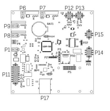
The BMS Main 2.1 headers
P1 – header for power supply
![]()
| Pin | Name | Description |
| 1 | GND | Ground |
| 2 | V+ | Supply voltage 9-30V |
P15 – header for BMS Logic

| Pin | Name | Description |
| 1 | RS485_A | RS-485 line A for communication with BMS Logic |
| 2 | RS485_B | RS-485 line B for communication with BMS Logic |
| 3 | +5V | Supply voltage for BMS Logic |
| 4 | GND | Ground |
P12 – header for current sensor

| Pin | Name | Description |
| 1 | +5V | Supply voltage for the current sensor 5V, max 50 mA |
| 2 | GND | Ground |
| 3 | Vcs | ADC input (current sensor output) |
| 4 | Vref | ADC input (current sensor reference signal) |
P13 – header for humidity sensor

| Pin | Name | Description |
| 1 | +5V | Supply voltage 5 V, max 50 mA |
| 2 | GND | Ground |
| 3 | Vhs | ADC input (humidity sensor output) |
| 4 | Vts | ADC input (temperature sensor output) |
- P8 – header of relay 1
By default, relay 1 is used to control the discharging contactor.
| Pin | Name | Description |
| 1 | V+ | Switching voltage (up to 55V, max 2A) |
| 2 | NO | Normally open contact |
- P9 – header of relay 2
By default, relay 2 is used to output the “Allow charging” signal.
| Pin | Name | Description |
| 1 | V+ | Switching voltage (up to 55V, max 2A) |
| 2 | NO | Normally open contact |