
Installation and connection
Installation
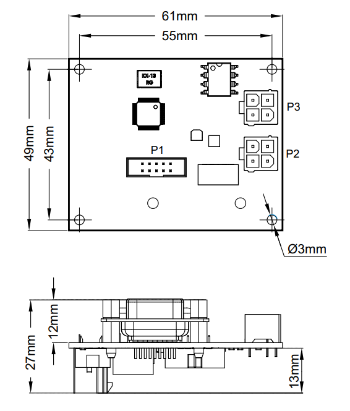
The BMS Indication 2.x has two headers for connecting the BMS (P2 and P3), a header for connecting external equipment (a PC, for example), and a switch which connects a terminal resistor to the CAN bus (SWD1).
| Parameter | Value |
| Overall dimensions (length × width × height), mm | 61 × 49 × 27 |
| Mounting dimensions (length × width), mm | 55 × 43 |
| Mounting holes | M3 |
| Header types | Molex series Mini-Fit, DB-9F |
Headers
P2, P3 – headers for communication with BMS

| Pin | Name | Description |
| 1 | CANH | CAN H line for communication with the BMS controller |
| 2 | CANL | CAN L line for communication with the BMS controller |
| 3 | +5V | Supply voltage 5 V |
| 4 | GND | Ground |
J1 – header for external equipment

| Pin | Name | Description |
| 1 | - | - |
| 2 | CANL | CAN L line for communication with external equipment |
| 3 | - | - |
| 4 | - | - |
| 5 | - | - |
| 6 | GND | Ground |
| 7 | CANH | CAN H line for communication with external equipment |
| 8 | - | - |
| 9 | - | - |
SWD1 – CAN terminal resistor switch
To connect the terminal resistor between the CANH and CANL lines, switch the SWD1 to the ON position.